
Deploying VMware NSX with Cisco ACI as the Physical Switch Fabric Design Guide (Version: 2024)
Introduction
This VMware NSX® design guide offers an enhanced solution for deploying NSX networking and security virtualization with Cisco ACI as the IP switch fabric. The intended audience of this paper is network and virtualization architects interested in deploying NSX network virtualization solutions. NSX is the leading SDN solution for the data center, providing multiple-site cloud networking and security. NSX is a game-changing solution designed to solve the complex challenges of multi-cloud networking and security—all while being easy to operationalize via a single pane of glass. Networking and security are critical to achieving scale with the cloud operating model.
This guide provides guidance and best practices for leveraging NSX with Cisco ACI. NSX runs over any physical switch fabric. This document aims to provide the prescriptive physical switch fabric setup with data centers running Cisco ACI switching for the most significant amount of interoperability of the VMware Cloud Foundation running NSX and vSphere infrastructures with NSX.
Applications Drive Infrastructure Requirements
The digital business era has increased the need for speed and efficiency in application development and customization. IT must provide expedient delivery, service, and security to keep pace, as customized application delivery directly impacts an organization's success.
- Inherent infrastructure firewall model - Securing application flows, whether east-to-west or north-to-south, and the security policy should be ingrained in the infrastructure. Applying appropriate per-flow policy is operationalized by writing rules applicable to the context of each workload. Each endpoint in a workflow attains policy in its inherent and natural connectivity to another endpoint. Service graphs and policy-based redirects are not inherent architectural methods for policy enforcement. These latter methods are tedious and often operationally do not scale, are difficult to troubleshoot, and often result in more prolonged mean-time-to-repair operations.
- Infrastructure independent – Deploying applications with diverse needs is a chore unto itself. Legacy deployment schemes have bonded the viability of an application to specific physical components of the switched fabric. This creates inherent dependencies for servicing and securing applications. Legacy hardware application deployment models added operational variances based on the physical devices of a site. Untying the infrastructure's application allows a cohesive operational model to be used across all sites regardless of the infrastructure. Cloud-based IT operational models are moving toward adherence to an agnostic approach to hardware infrastructure.
- Security everywhere – Perimeter security models have proven insufficient, as evidenced by the numerous reported exploits occurring deep within the data center and the cloud. The security policy must concern itself with attacks from the public to any site and location and protect all dependent application flows and the ever-increasing east-to-west communication paths. Security must also position every workload as its own demilitarized zone (DMZ). Security must wrap around all application frameworks and their respective tiers, using traditional virtual machine deployments, bare-metal, containers, and microservices composing the newer cloud-native applications.
- Diverse application frameworks, sites, and clouds – As previously mentioned, application development is accelerating. Adding new frameworks, including PaaS, modern application frameworks, and a hybrid set of sites inclusive of clouds, requires an innovative approach to networking and security. A software-only network virtualization solution aids the agility that IT operations require for various tasks. The moving or failing over workloads between diverse locations, managing an ever-changing set of application frameworks, and a need for extensibility to introduce new services and features are only a fraction of these tasks.
- New*** NSX Multi-Tenancy Framework—NSX introduced a multi-tenancy framework in NSX 4.1 and 4.1.1. The native multi-tenancy in NSX 4.1.0 allows multiple users to consume the platform in parallel without the risk of overlap or disruption. This makes it possible to provide users with direct access to NSX but segments each within isolated environments where they can configure their own NSX objects and apply rules only to their workloads.

NSX Network Virtualization Considerations
Easing the burden of data center architecture solutions is at a turning point. Solutions before this modern era introduced modest, gradual, and somewhat evolutionary changes. A new mindset began whereby a software-defined network managing a virtualized network became the desired norm. VMware NSX introduced the first fully software-only, hardware-independent approach to solving this need. With the mainstreaming of VMware NSX network virtualization and an adoption rate second to none, NSX exemplifies the approach to solving network and security problems within the data center. Further, this desire rapidly evolved beyond data center operations for application deployment, security, and availability to a holistic view of operationalizing the primary data center operations, multiple sites, the network edge, and across the cloud.
By leveraging a software-defined, programmable network via NSX, the modern data center network combines networking virtualization plus storage and compute virtualization to realize the full potential of the software-defined data center (SDDC). Figure 1 displays the integration of network virtualization and security with other core platform components of VMware Cloud Foundation.

Figure 1: NSX as the core networking and security component of VMware Cloud Foundation
NSX is the de facto standard for defining a network virtualization platform in the software-defined data center (SDDC). It delivers a more agile operational model for vSphere-hosted virtual workloads and transforms the economics of network and security operations. NSX lets you treat the physical network as a pool of transport capacity without specific features to alleviate attaching network and security services to various physical and virtualized appliances. NSX contains the VMware Firewall and the VMware Firewall with Advanced Threat Prevention that delivers policy via standardized networking with no logical or physical modifications required for policy enforcement.
NSX virtual networking runs atop a physical IP switch fabric supported by any networking vendor. IT teams look to automate the network required for workload connectivity as data center networking evolves. But too often, the ideals of software-defined networking are entangled with a complex hardware-switched dependent model to deliver a software-defined experience. Cloud-like networking solutions do not have a dependency linked to the physical network. Research analysts, legacy-minded network professionals, and others who define it in such ways disregard the market or customers they purport to serve. Customers choosing a hardware-dependent solution have suffered the inevitable delays for fabric deployment and application delivery, extended scoping of troubles encountered, increasing mean-time-to-repair operations (MTTR), and driving IT teams to alternative cloud solutions. For instance, customer X's guest network team chooses a hardware SDN switch model yet fails to deliver applications at speeds required of the business due to one or more of the following issues:
- Overwhelming solution complexity, delaying deployment
- Unforeseen operational overhead of required services promised by the hardware-bound physical network to enforce security policy
A fully software-defined model decouples the physical infrastructure from the application's dependency requirements to simplify the physical network's operations. Reducing the application's dependencies on hardware-defined assets provides flexible service deployment for a more agile workload consumption approach. Reducing hardware dependency is the heart of the cloud service consumption value in an application-centric deployment and service model.
This document guides networking and virtualization architects interested in establishing a programmable network with the full functionality of NSX networking and security while using Cisco ACI for the physical network. While neither solution is dependent on the other, some dependencies ensure interoperability. This paper discusses the fundamental building blocks of NSX with VMware vSphere and ESXi™ and provides a prescriptive configuration for the Cisco ACI switch fabric.
Further, this document continually provides necessary updates, extensive additions to our reference design for NSX networking on Cisco ACI, and helpful best practices. Pictures detailing configuration and a more detailed discussion of the required configuration elements are included.
Necessary: The reference guidance provided in this document facilitates a stable, resilient physical switch fabric. Any deviation from the recommendations may cause challenges in the deployment and operations of both NSX-T and the Virtual Cloud Foundation deployed on a Cisco ACI fabric because the Cisco ACI fabric is not a typical networking deployment. Utilizing the deployment guidance offered in this document normalizes the Cisco ACI fabric, reduces the deployment timeframes, alleviates complexity, and removes the introduction of inappropriate hardware entanglements in managing the SDDC stack of the vSphere environment.
NSX is agnostic to any switch fabric, including any Cisco Data Center Nexus switching. We recommend deploying NSX on standardized switch fabrics like Nexus switches running NX-OS. Cisco NX-OS allows flexibility of topology and features supported by various 9000 series Nexus switches, including the legacy Nexus switching (Nexus 56xx, 6xxx, 7xxx, 3xxx, and older 9xxx series). Fabric management with Cisco Nexus Dashboard can provide much the same in fabric automation.
- Design Guide for NSX with Cisco NX-OS and UCS (coming)
These guides provide overall design guidance for NSX deployments for NSX across one or more sites:
This document assumes that the customer understands Cisco ACI and NSX well. Table 1 provides a complementary view of the capabilities provided by NSX and Cisco ACI when used in conjunction with one another. Customers have requested such interoperability as it gives them the full benefit of a software-defined programmable network overlay with NSX Data Center, easing the automation of networking and services. At the same time, it provides an inherently embedded adaptive micro-segmentation feature set of virtual and physical workloads. Cisco ACI enables customers to build and control the physical underlay fabric.
|
Full NSX Features |
Cisco ACI Underlay Features |
|
|
Table 1: VMware value proposition with NSX and Cisco ACI contributing features
IMPORTANT:
Cisco ACI has multiple modes of operation. Cisco ACI's "network-centric" operational mode provides the least complex interoperable solutions. Cisco ACI in network-centric mode provides the greatest compatibility and interoperable servicing for VMware Cloud Foundation and vSphere with NSX. VMware delivers a supported model, which is outlined in this document. More specifically, the following methods or service features are not supported:
- There was never support for Cisco Application Virtual Switch running on VMware vSphere® 5.5, vSphere 6.0, or vSphere 6.5 in any vSphere deployment.
- Cisco Nexus 1000v cannot be used with NSX and is deprecated as of vSphere 6.5.1. Installation will not be possible for future vSphere releases.
- VMware vSphere Distributed Switch™ cannot be controlled by the Cisco ACI plug-in nor Cisco ACI Virtual Networking (otherwise known as Virtual Machine Management, VMM). ACI VMM was developed independently and is outside the partner support model VMware by Broadcom has in place. All support and subsequent risks for using ACI VMM will be handled solely by Cisco. See the Cisco documentation about out-of-synchronization issues that can arise from using VMM. VMware supports using vSphere APIs for VDS management and operation, but not the unintended extensions imposed by split-brain operations from third-party integrations such as Cisco ACI VMM.
- Cisco Nexus 1000VE is not supported,
NOTE: For supported interoperability of the listed VMware technologies such as VMware vSphere and the vSphere Virtual Distributed Switch, VMware Kubernetes for vSphere, Tanzu Kubernetes, Tanzu Kubernetes Grid (TKG), Tanzu Kubernetes Grid Interface (TKGI), NSX, and vSphere Distributed Port Groups managed via NSX Manager that are either VLAN or Overlay backed Distributed Port Groups must never be provisioned by an integrated API or by an unsupported third party Center Plug-in with the management of the physical switching. VMware by Broadcom will support automation of the vSphere distributed switch and its objects when there is a clear line of demarcation from the switch fabric and managed independently from the physical switching fabric. Cisco ACI utilizes ACI VMM for its Cisco Virtual Networking, which may involve virtual machines, containers, and service virtual machines such as the Cisco ACI Virtual Edge (Cisco AVE). Cisco AVE requires Cisco ACI VMM as it is a dependent setup feature for Cisco AVE.
VMware by Broadcom advocates an on-premises private cloud environment free from the entanglements of the physical infrastructure.
A more in-depth discussion of the management of the vSphere Distributed Switch is found in section 1.4 Native Distributed Switch Management.
NSX and Private Cloud Networking
Traditional enterprise networks were built by connecting physical devices—computers, servers, routers, and switches—to each other. After setting up a network, security solutions were bolted on at the end. Manual changes to the network were necessary to institute security policy. Thus, leaving a wide margin for error and increasing the potential for costly outages.
The emergence of software-driven networks has challenged these existing norms. Modern technologies allow software abstraction of a network's hardware-based feature set. Automation and programmability minimize a company's operational complexity by replacing complicated manual tasks, enabling better scale and reliability. Today's advancement of software-defined networking provides businesses a means to modernize their network with software and open a new set of possibilities driving business innovation.
Most of today's enterprises use or plan to use multiple clouds to run their business. Everything of value connects to the network and delivers new customer experiences through the cloud. Users connect not only through their desktop and laptop computers but also via mobile devices. Applications run everywhere across a company's infrastructure. Yet, many companies don't clearly understand the security and connectivity of their applications and devices across the data center, branch, cloud, and edge.
These emerging technology trends increase enterprise security complexity and challenge the limitations of hardware-driven networks. Software-based networking creates a business fabric that securely and consistently connects a company's data centers, carrier networks, branches, endpoints, and clouds. And it's all done independently of the underlying network hardware.
Virtual networks run more efficiently and lower operational costs by automating network infrastructure functions such as maintenance, patching, and updating. They also increase uptime, improve service, and reduce costs—enabling organizations to maximize the value of their existing network hardware while creating innovation and business opportunities.
In addition to automating data centers, companies are turning to virtualized networks to improve security. With software, security policies can be set once and deployed across the network, following applications, services, and devices wherever they go. Technologies such as micro-segmentation, which enables security around individual workloads, provide additional protection.

Figure 2: VCF Networking by NSX is the cloud network operating model with network visibility to your on-premises data center
The positioning of NSX as the virtualized network solves these challenges as NSX brings networking and security closest to the workload and carries the policies along with the workload. NSX's unique ability enables customers to solve bona fide business problems. When customers deploy NSX with Cisco ACI as the underlay, they can get all these incremental benefits, which is impossible with an automated hardware underlay-based solution.
Let us now look at some of the critical technical benefits, requirements, and operational aspects of NSX.
1 NSX Architecture and Operations
NSX enables private cloud teams to build logical services for networking and security on any infrastructure or site without making configuration changes to the physical infrastructure to deploy new workloads. For example, once the Cisco ACI fabric is configured to provide IP connectivity and the routing configuration is provisioned in this design, secure application workload deployments proceed with NSX. No operational modification of the Cisco ACI physical switch fabric is required for the most part. However, a mistakenly inherited function of any hardware-defined architecture is the operational differentiation required for transitioning a private cloud model across sites with heterogeneous hardware, sites with managed hardware services, or managed providers with disparate switch hardware.
NSX is architected for any site, device, and application framework. As NSX matures, updates and new features enhance these highly important aspects. NSX achieves operational symmetry by abstracting the endpoints and providing a common framework for policy operations, and software is driving the model. NSX has already achieved a framework for policy management across on-premises private clouds to resources extending into multiple hyperscaler partners.
As the first SDN software-only network platform, NSX implements three separate but integrated planes: management, control, and data. The three planes are implemented as sets of processes, modules, and agents residing on two types of nodes: manager appliances and transport hosts.

Figure 3: NSX SDN Architecture for Private Cloud, VMs, Containers
The following section provides an overview of the NSX functional features and primary use case examples showing how applications can be deployed with NSX as the network virtualization platform of today’s SDDC.
1.1 Manager Operations
The management plane for NSX-T is a cluster of three NSX-T Managers provided in a virtual machine form factor. The NSX-T Manager provides the following functions:
- The manager provides an aggregated system view and is the centralized network management component for the NSX ecosystem.
- The management plane provides a single API entry point to the system via RESTful API or their respective user interfaces.
- The management plane persists user configuration, handles user queries and performs operational tasks on all management, control, and data plane nodes in the system.
- The management’s virtual appliance is responsible for storing the desired configuration in its database.
For a more in-depth understanding of the management, control, and data plane components of the respective NSX platforms, please review:
1.2 Control Plane Operations
NSX provides a multicast-free overlay connectivity for logical switching and routing with control plane functionality provided by a highly available controller cluster. Removing the necessity of layer 3 multicast from the underlay network greatly simplifies physical network configuration. Additionally, the controller cluster services distributed discovery and efficient management of control plane functions for the NSX overlay. These services provided by the highly available clustered controllers are MAC, VTEP/TEP, and ARP table management and distribution of dynamic routing, collected from the distributed router control virtual machine.
Terminology
- NSX Data Center for vSphere uses a VTEP (virtual tunnel endpoint) for its VXLAN overlay.
- NSX-T Data Center employs a TEP (tunnel endpoint) for its Geneve overlay.
Either overlay, VXLAN or Geneve, used in all versions of NSX is agnostic to the underlay. The underlay fabric is only required to provide IP connectivity for the tunneling endpoints used by the respective overlays of NSX. Our NSX designs require only a highly interoperable switch fabric with an appropriately set MTU that any switch fabric vendor provides.
1.3 Logical Layer Connectivity
NSX logical layer connectivity offers drastic improvements over legacy physical deployment models. Leveraging an overlay allows logical layer 2 segments over physically routed environments. Layer 2 adjacency is no longer tied to the physical infrastructure that can be switched or routed, yet an overlay network enables VMs to be in the same subnet, layer 2 adjacent, and providing topology-independent connectivity. This enables mobility beyond the structured topology constraint imposed by physical networking. NSX logical layer 2 adjacency does not require complicated underlay management or control plane operations.
Figure 4 displays a series of logical layer 2 segments with layer 2 adjacent virtual workloads spread across multiple physical hosts situated on three separate routed subnets.
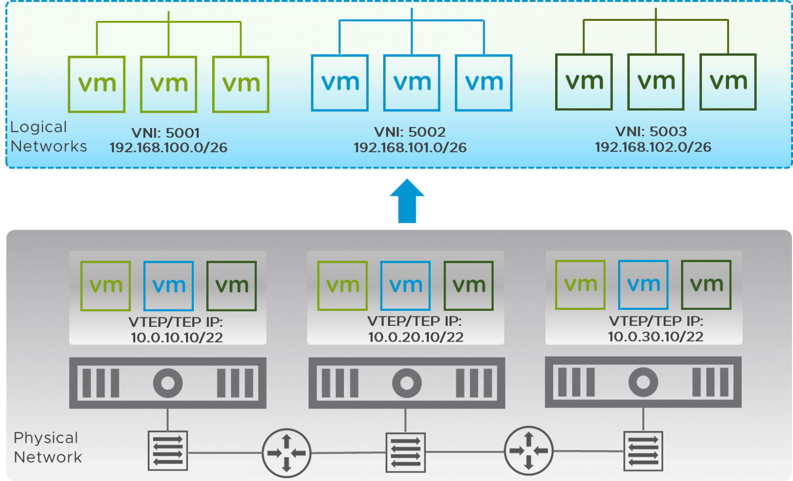
Figure 4: Logical Layer 2
NSX Data Center builds multicast-free VXLAN-based (NSX Data Center for vSphere) and Geneve-based (NSX-T Data Center) overlay networks requiring no Spanning-Tree (STP). This layer 2 adjacency between the VMs can be established independent not only of the physical network configuration, but the hypervisor (vSphere or KVM), the site, and across cloud(s), including VMware Cloud™ on AWS (VMC on AWS) and VMware NSX Cloud™. Extending this network across these deployment targets, as shown in Figure 5, demonstrates that NSX Data Center allows a diverse target environment to be managed under a single policy platform.
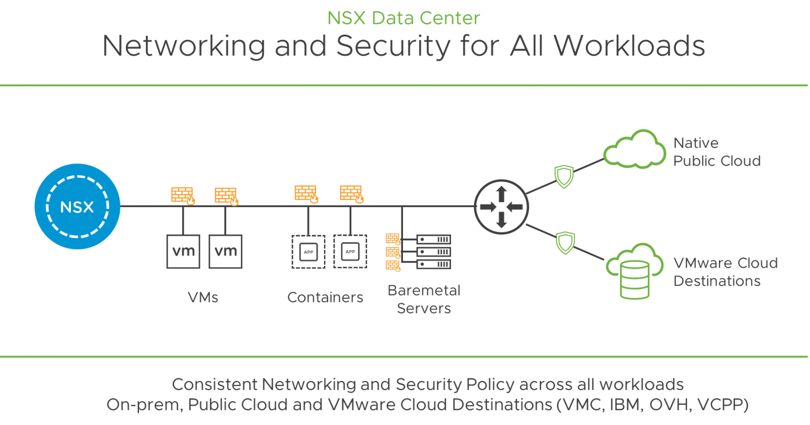
Figure 5: NSX Data Center, Securing Deployment Targets Across a Diverse Environment
NSX logical networks provide the basis for a programmable network. New logical networks are created upon demand via NSX integration or use of NSX APIs with various cloud management platforms (CMP), open source platforms, and scripting tools. NSX logical networks can be brought up and torn down when necessary without underlay entanglements or operational overhead. By decoupling the logical networks from the physical network topology required for workload communication, the application is truly the center of attention for service management, accelerating the business needs to a realized functional application.
1.4 Native Distributed Switch Management
One of our key requirements for a successful and validated deployment of NSX is that the virtual switching should be managed by native services of the NSX Data Center deployment. Although the virtual distributed switch is one component leveraged in network virtualization, it is an essential component in offering our customers operational simplicity and rapidity in network configuration for application deployment. Further, most importantly, NSX Data Center leverages the kernel services of the hypervisor to instantiate a high-performance distributed firewall capable of stateful and contextual application security. Validating the insertion of any service positioning itself into the process of configuring a component feature of such importance would be the prime concern of any vendor for its product.
Operationalizing the deployment distributed switch of the VDS used by NSX Data Center for vSphere, or the N-VDS of NSX-T, can leverage a variety of UI, scripting, and automation tools. These tools are available through VMware, partner-validated products and services, or open source. What should never be considered for support by any vendor are operational tools that necessitate the configuration of a vendor’s asset central to its purpose through a non-partner-created service or product. For NSX Data Center, instability and other eventful disasters can be mitigated by avoiding the use of tools that use stateful reproduction of the VMware virtual distributed switch through unsupported event replication or synchronization processes.
Cisco ACI has a feature commonly referred to as a Virtual Machine Manager Domain or VMM. VMware strongly recommends against the use of this feature for creating and managing the vSphere Distributed Switch for NSX Data Center deployments. It is not tested for the designs in this document. VMM was created independently by Cisco outside the VMware partner support program, so any side effects, risk, and support would come solely from Cisco. This includes all aspects inclusive of modes, virtual distributed switch versions, and the use of Cisco Application Virtual Edge (AVE). See the Cisco documentation about out-of-synchronization issues that can arise from the use of VMM domain management.
VMware strongly recommends against the use of VMM domain management when Cisco ACI underlay is the chosen fabric manager. Cisco ACI can be deployed with a more practical approach using a stable “network-centric” management interaction with compute deployment. Network-centric management treats all connectivity with a VLAN-backed connection to an endpoint group (EPG). This style of ACI deployment provides the ideal usage for automation in managing the underlay and normalization of its operations.
VMware Cisco ACI VMM/AVE Mode Support Statement
VMware supports vSphere and all features available through the public API.
Any API-level integration implemented outside of a certified partner program is a customer’s responsibility and is not supported by VMware.
Cisco ACI VMM/AVE leverages the vSphere APIs but was developed outside of any formal partner program and therefore is not supported by VMware.
For Support Requests which directly relate to the ACI VMM/AVE component and how it interacts with vSphere, VMware will request that the Cisco VMM/AVE component be removed for troubleshooting purposes as per the VMware Third-Party Hardware and Software Support Policy.
- If the issue is reproducible without the Cisco VMM/AVE component, VMware will support and investigate as normal.
- If the issue is not reproducible when the ACI VMM/AVE component is removed, VMware will not investigate further.
Source: Cisco ACI AVE/VMM Mode Support in a VMware environment (57780).
Disaggregation of the virtual switching and the overlay from the physical fabric has been the hallmark of NSX Data Center designs. This disaggregation lends stability to the underlay fabric services while providing the preferable cloud-centric approach in abstracting the virtual network from the physical infrastructure.
1.5 Distributed Routing
NSX Data Center employs a dual-tier routing made of centralized and distributed routing components. Centralized routing is used for on-ramp/off-ramp functionality between the logical network space and the external L3 physical infrastructure. Distributed routing provides high-performance routing for east-to-west traffic flows.
NSX enables distributed routing and forwarding between logical segments within the hypervisor kernel, as shown in Figure 6. In this topology, three different logical networks are isolated in three different subnets. Using the distributed routing functionality provided by NSX, these subnets are interconnected without the overhead of routing integration changes with the underlay.

Figure 6: Distributed Routing with NSX Data Center
NSX-T high-performance two-tiered routing architecture is composed of T0 and T1 router instances, with T0 providing top-level connectivity and T1 used for tenant-level connectivity when necessary. Also, NSX-T T0 to T1 tiered routing instances are autoplumbed, including all logical networks connected to a downstream T1 router whenever a T1 router is employed. Dynamic or manual configuration of the static routes for distributed routing between the tiers in NSX-T is unnecessary due to this autoplumbing of routes.
NSX-T does not require the use of T1 routing. T0 routing can provide distributed routing and centralized routing for on-ramp/off-ramp functionality between the logical network space and the external L3 physical infrastructure. T0 routing is required for this purpose and discussed later in the NSX Edge Routing to Physical Infrastructure section. T1 routing provides an additional layer of tenant-level routing in addition to service-level placement. T1 routing is optional.
NSX Data Center for vSphere also employs a dual-tier routing structure of centralized and distributed routing. Distributed routing is fulfilled by two components:
- Control plane virtual appliance for dynamic route control plane servicing and distribution of the learned dynamic routes to the NSX Controllers
- Data plane element embedded as a high-performance distributed kernel component within all prepared hypervisor hosts
Centralized routing is discussed in the NSX Edge Routing to Physical Infrastructure section.
The key benefit of distributed routing is an optimal scale-out routing for east-west traffic between VMs. Each hypervisor has a kernel module that is capable of a routing lookup and forwarding decision performed at near line rate. As shown in Figure 6, traffic within a single host can be routed optimally within the host itself when the VMs are located on separate logical switch segments. The localized forwarding reduces traffic to the ToR (top of rack) and potential for reduced latency as packets are switched in memory.
Traffic required to traverse the physical fabric will use the ACI ToR to make a forwarding based upon the destination VTEP or TEP IP where the remote virtual workload is hosted. But in a classic architecture, all routed traffic would be forwarded to the switch with the SVI configuration to make a forwarding decision for all virtual workloads. NSX distributed routing reduces this necessity, provides a simpler traffic view for the infrastructure to manage and operate, and thereby reduces I/O usage of the physical fabric.
In addition, as previously noted, the distributed router scale-out capability supports multi-tenancy in which multiple distributed logical router instances can be invoked to provide routing-control plane separation within the shared overlay infrastructure. Figure 7 shows a common topology use case where tenant-level routing is separated using NSX Data Center two-tiered routing capabilities.

Figure 7: NSX Two-Tiered Routing Separating Route Control Plane of Individual Tenants
NSX not only abstracts away the issue of physical layer 2 adjacency with its overlay networking, NSX further abstracts layer 3 connectivity with high-performance distributed routing.
1.6 NSX Edge Routing to Physical Infrastructure
As we have seen, NSX distributed routing will provide routing between virtual workloads, and when necessary between workloads located within separate tenants. To route from the logical network to the physical network, NSX can learn and exchange routes with the physical infrastructure. Edge routing provides routing workflows from the overlay to physical resources such as a database server, other non-virtualized workloads, and access to networks beyond the data center.
NSX can provide scale-out routing leveraging Equal Cost Multi-Path (ECMP) between the NSX distributed router and the VMware NSX Edge™ cluster, in addition to ECMP with the edge cluster and the router instances of the physical infrastructure. The NSX edges peer with the physical routers using static and dynamic routing, providing either administratively managed connectivity with static routing or scaling north-to-south bandwidth with ECMP-based routing. Figure 8 displays routing from the NSX logical network to the physical network using an edge topology configured for ECMP.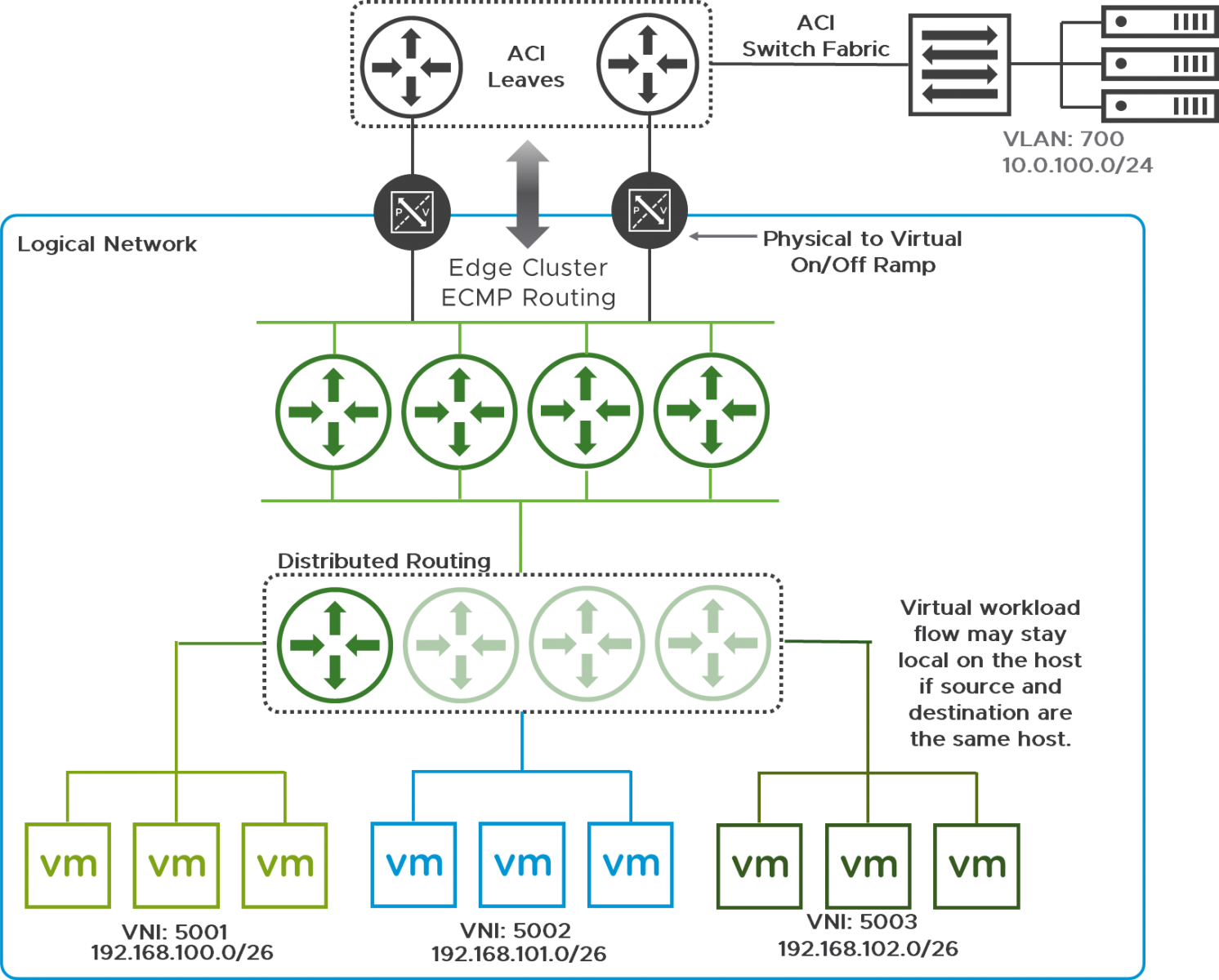
Figure 8: Edge Cluster with ECMP Routing to the Physical Fabric
The ROI attained by the use of NSX Edge routing is accomplished through multiple operational aspects. NSX Edge routing adds stability to the physical network infrastructure through
- Adding and scaling out workloads will require no modification to the physical infrastructure.
- Deployment of services such as NAT, load balancing, DNS, DHCP, VPN, and firewalling also require no modification to the routing or switching functionality of the physical infrastructure.
- Service deployment is completely disaggregated from the physical infrastructure, providing a true private cloud service when deploying workloads.
- Operational servicing of the physical infrastructure is substantially reduced, allowing time expenditure of IT teams to be focused on servicing the application.
- Workload dependency from a physical location is fully realized with the edge cluster service, thereby attaining true application agility.
NSX Edge routing adds centralized servicing of north-to-south traffic flows, service deployment for services performing a centralized function, and a disaggregation of the private cloud deployment of the virtualized network.
1.7 Security with NSX Distributed Firewall
Instantiating a distributed firewall service upon the VMware distributed switching virtual switch is more than just labeling a service or product as a distributed firewall. NSX institutes a stateful firewall offering contextual feature additions at near line-rate performance. Operational simplicity is assured through a modest set of requirements for a successful deployment of NSX for adaptive micro-segmentation. This is one of the main reasons NSX is used to solve a variety of security use cases. Further, NSX can provide a useful service to aid in the migration of the customer’s data center to its new fabric underlay. Running an NSX platform establishes a software-defined data center and requires only solid IP connectivity from the fabric underlay.
NSX, by default, enables the distributed firewall in the kernel, which is realized at the vNIC of each VM. Ingress or egress traffic from the VM will always traverse the distributed firewall. Key benefits include a stateful layer 2 through 4 firewall, and the reduction of security exposure at the root of east-to-west traffic that is isolated from the virtual workload, but with excellent context regarding the workload’s use. Context-aware firewall services through App ID ensures layer 7 provides the identified service of layer 4. The NSX distributed firewall’s inherent software services layer offers an adaptive micro-segmentation capability.
The distributed firewall can supplement a centralized firewall at the periphery of the data center, and remove physical (or concrete) devices used as an east-to-west firewall that require complex service graphs for operational use. Use of these periphery firewalls polarizes traffic to specific regions of the switch fabric in order to stitch IP traffic through them.
The NSX distributed firewall adds the following benefits:
- Eliminates the number of hops while reducing bandwidth consumption either to and from the ToR or when pushing IP traffic to designated remote locations of the switch fabric, while forcing application flows to traverse a centralized firewall
- Flexible rule set applied dynamically, leveraging multiple object types available to NSX security management, such as a logical switch, a cluster dvPortgroups, security tags, virtual machine attributes and more
- Allows the security policy and connection states to move during automated or manual moves with VMware vSphere vMotion®
- A spoofguard policy adjacent to the virtual workload not possible with a physical firewall
- Stateful filtering of ingress and egress traffic at line rate
- Fully API capable for developing an automated workflow leveraging programmatic security policy enforcement at the time of deployment of the VM through a variety of cloud management platforms, based on exposure criteria such as tiers of security levels per client or application zone
As shown in Figure 9, the architect now has flexibility in building a sophisticated security policy because policy is not tied to physical topology. The security policy can be customized for inter- and intra-layer 2 segment(s), complete or partial access, as well as to manage N-S rule sets that are employed directly at the virtual-workload level. The edge firewall can be used as an interdomain security boundary.

Figure 9: Micro-Segmentation and Protection of Traffic
The NSX micro-segmentation distributed firewall policy capability as shown in Figure 9 has many advantages, such as
- Creating PCI zones within shared segments
- Contextual security policies such as Identity Firewall for desktops in a VDI environment
- Reducing operational overhead required for stitching traffic through centralized firewalls with legacy policy-based routing rules
- Virtual demilitarized zone-based firewalls per every workload
- Security policy centrally managed for multiple sites
- The same security policy used across private cloud, hybrid cloud, and public cloud workloads
NSX adaptive micro-segmentation eliminates or reduces
- Scaling limitations imposed by switch TCAMs for storage of access-control lists entries
- Use of legacy-style PVLANs to provide intra-tier segmentation compounding the complexity with proxy-arp added contracts due to sub-groupings
- Use of an array of complex security construct combinations of security groups, micro-segmentation groupings, PVLANs, and proxy-arp all to achieve stateless, reflexive access-control filtering
- Combining use of strongly not recommended virtual distributed switch management services with user space L4 filtering appliance services and PVLANs, that are still limited to the capacity of legacy TCAM space consumption
There are many workarounds combined with line cards and switches with larger and larger TCAM entries that have attempted to scale TCAM. These include dynamic provisioning, use or non-use of a reflexive setting, and combining security rules to apply to a larger endpoint grouping. The designs in this document propose a simpler and more inherent approach with the use of software first for the larger set of dynamic virtualization workloads, virtual-to-physical and physical-to-virtual micro-segmentation. Physical-to-physical segmentation can be covered by traditional firewalling where deep inspection is needed, and ACI segmentation where stateless inspection is acceptable. VMware NSX is adding adaptive capabilities to begin securing physical workloads.
Note: For additional information, see VMware Network Virtualization Blog: Extending the Power of NSX to Bare-Metal Workloads.

Figure 10: NSX Firewalling Model
The NSX adaptive micro-segmentation security model provides its services in a software-driven, API-capable, scalable model. NSX micro-segmentation uses stateful segmentation of each individual workload, regardless of the number of application tiers, flat or routed topology, or dependent services. Micro-segmentation involves the ability to inherently position firewall services beyond layer 4 filtering. NSX distributed firewall and adaptive micro-segmentation provides contextual awareness to security admins offering even deeper granularity of security policies. This context-awareness includes
- Native layer 7 firewalling services for east-to-west communications
- User-identity-based security for virtual desktop environments
- Per-user/session-based security for Remote Desktop Session hosts
NSX adaptive micro-segmentation has raised the bar for east-to-west workload security above all peers, which mainly provide stateless, reflexive access. Figure 11 displays the adaptive micro-segmentation model of integrating all services: overlay network isolation, distributed firewall segmentation, and the use of service insertion.

Figure 11: NSX Micro-Segmentation Platform
A substantial additional value-add is the relative ease in integrating additional L7 deep-packet network inspection and guest introspection. NSX uses a simplistic model with a transparent path for the extended security inspection service, and is rendered local to the source hypervisor of the targeted virtual workload. NSX redirection to L7 guest and network introspection services completes the needs of micro-segmentation without stitching IP pathways or complex network service graphs.
1.8 Flexible Application Scaling with Virtualized Load Balancer
Elastic application workload scaling is one of the critical requirements in today’s data center. Application scaling using a traditional physical load balancer often lacks the sufficient agility for modern application needs, given the dynamic nature of self-service IT and DevOps-style workloads. The load-balancing functionality natively supported in the NSX Edge appliance covers many of the practical requirements required to provide application availability and performance enhancements. NSX load balancing can be deployed programmatically based on application requirements with appropriate scaling and features. The scale and application support level determine whether the load balancer is to be configured with layer 4 or layer 7 services, using application rules and a wide spectrum of additional servicing.
Each instance of the load balancer is an edge appliance that is deployed either using the NSX Manager UI, or dynamically defined via an API as needed and deployed in high-availability mode. Topology wise, the load balancer is deployed either in-line or in single-arm mode. The mode is selected based upon specific application requirements.
The single-arm design offers extensive flexibility as it can be deployed near the application segment and automated with the application deployment. Single-arm load balancing does not require a modification of the IP addressing used for the application communication.
Figure 12 shows the power of a software-based load-balancer using single-arm mode. Multiple single-arm mode instances of the load balancer serve multiple applications and a single instance can serve multiple segments.

Figure 12: Logical Load Balancing per Application
Alternatively, the load balancer can be deployed using in-line mode, which is able to serve the entire logical domain. Scaling the in-line load balancer is done by enabling a tiered edge instance per application. Each application can be a dedicated domain for which the tiered edge instance acts as a gateway, a load balancer, and if desired, a stateful firewall for the application. A provider set of edges are configured as an ECMP gateway for scalable north-south bandwidth.
As one can observe from Figure 13, the first application block on the left is allowing a single-arm load balancer with distributed logical routing. The center and the right blocks of the application allow an in-line load balancer that is either routed or routed with NAT capability respectively. The top-tier edge cluster is enabled with ECMP mode to allow north-to-south flow capacity to scale on demand from 10 Gbps to 80 Gbps and much higher through hardware offloads such as DPDK.

Figure 13: Scaling Application and Services with NSX
The provider edges offer highly interoperable infrastructure connectivity while abstracting application deployment in the overlay from the physical infrastructure. This agility is an essential element of an SDN. The NSX edges and edge nodes provide routing, firewalling, and application services; as well as load balancer, NAT, DHCP, IP pools, and DNS proxy.
A large value-add for the NSX Edge cluster design models is the ability to deploy application-dependent services disaggregated from the physical infrastructure. A logical tenant model is attained with NSX edges that provide services near the applications, avoiding complex service graphing or network traffic stitching.
This type of agility cannot be provided through a hardware-defined switched underlay without considerably more operational management and complexity. This cannot be overstated enough as the cloud services model has shown this to be true. Security and service offerings provided by the NSX platform are easily scaled in and out as well as scaled vertically or horizontally, depending on the application needs. An NSX software-defined network virtualization platform affords a cloud service experience within the enterprise data center.
1.9 NSX Layer 2 Bridging from Virtual to Physical Infrastructure
Some application and service integration may require connecting VMs to physical devices on the same subnet (layer 2-centric workload connectivity). Examples include migrations to virtual workloads, migrating app-tiers on the same L2 network using hard-coded IP addresses, and some virtual workloads with L2 adjacency to application-integrated ADC appliances. Bridging the overlay to a VLAN can be accomplished by leveraging the native bridging functionality in NSX shown in Figure 14.
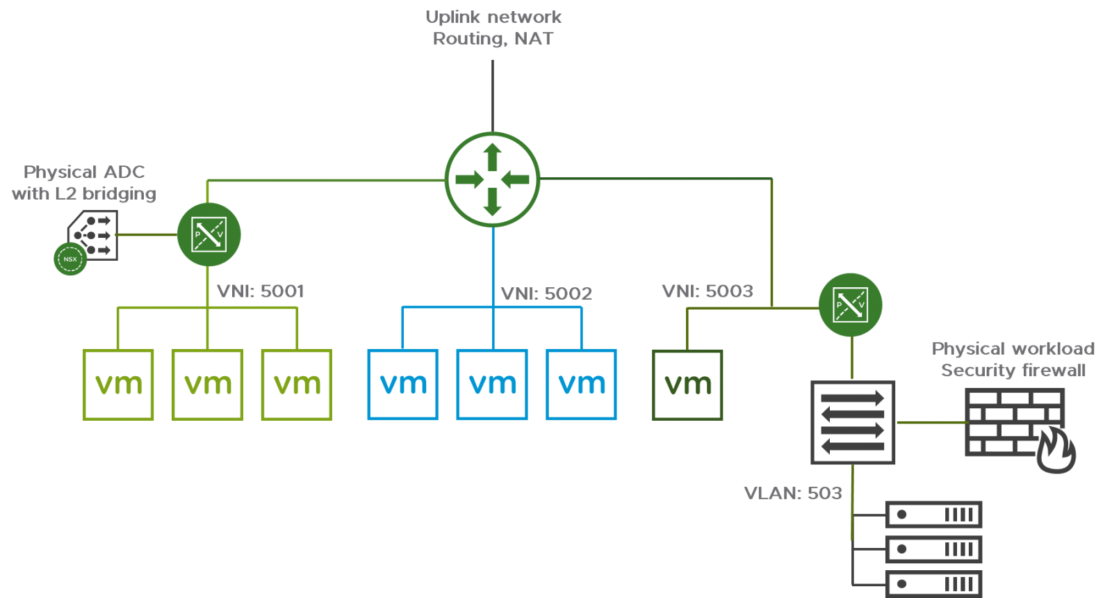
Figure 14: Layer 2 Bridging from Virtual to Physical
NSX layer 2 bridging design considerations are covered in the NSX design guide. Additionally, depending upon the use case, NSX supports either integrated hardware VTEPs or the use of multicast-based hardware VTEP integration. Either will require additional design considerations.
Note: Nexus 9000 switches running ACI do not support use as integrated hardware
1.10 Operations
Building upon the application topology discussion of the prior section, changes to the underlay are minimized. Further, changes that do happen during application deployment are scoped to the needs of the NSX overlay and rarely require modifications to the hardware switched underlay. The switch fabric experiences more stability and little to no need for hardware modifications or updates, for enhancing physically dependent service functions due to hardware limitations caused by fixed feature sets and physical maximums being breached.
Our goal is to reduce the amount of operational management of the physical fabric and hone the cloud team’s attention to application deployment and service management. The following lists the one-time operations for installation and deployment of the switch fabric. The NSX deployment would follow a high-level series of steps, performed by the Cisco ACI admin:
- Initial configuration for ACI fabric bring up
- Configuration of ACI fabric connectivity for the NSX data center operational clusters
- Management, Compute, and Edge
- For details of the setup of this specific set of system objects, see Cluster Connectivity for the NSX Infrastructure Clusters.
- Configuration of a single ACI tenant requiring the following
- A single Application (Network) Profile containing the necessary EPGs
- External domain routing for the NSX network virtualized overlay
- For details on this specific set of tenant-related objects, see Demystifying the Overlay Transport and IP Connectivity.
Configuring these few items within the ACI fabric normalizes its services with a network-centric deployment architecture. This simplifies the switch fabric management while leveraging the underlay automation. At this point, the cloud admin will perform the deployment and initial configuration for the NSX functional clusters and edge cluster routing with the ACI border leaves.
A few key items to note with this initial configuration:
- Virtual services can be set up without any change to the underlying physical infrastructure.
- The infrastructure environment requires little operational change save for scaling out additional compute and switch fabric assets as workload needs grow.
- This adds stability to the IP infrastructure for application deployment operations upon the NSX platform that follow.
The next course of action is operationalizing NSX and application deployment. This involves a variety of aspects such as optimizing the organizational structure and the corresponding IT organization’s operational processes to fully advantage the teams for NSX usage. Further consideration is needed for the users and applications brought onboard, the developer consumption models, and the tools that will be used by the users and developers.
We will concern ourselves with bringing the applications onboard and the use of several key tools in this section.
A discussion of the people, the processes, and tooling when operationalizing NSX can be found in the VMware blog, The Key to Operationalizing NSX.
For anyone attempting a task, whether it is upgrading a portion of your home or fixing a broken appliance, the tools to put into your toolbelt should be appropriate to the task at hand. For network operations and monitoring, traditional tools that provided flow analysis, packet capture, and network management were not created to operate in the modern virtual networks, much less multi-cloud environments. Due to the nature of network virtualization, end-to-end troubleshooting, visibility, scalability, and a security perspective should be built into the operational tool from its conception, not strapped or glued onto a traditional tool.
Running an NSX overlay over a Cisco ACI fabric presents nothing new. Cloud-based environments are built upon underlays that use their own encapsulation functionality, whether they are VLAN- or VXLAN-based. The underlay’s encapsulation service running VXLAN is often termed an “overlay,” but it is providing a service for endpoint communication from the physical system viewpoint. NSX overlays provide an application platform to service endpoint communication within the virtualized network.
With NSX, several tools are inherent in your toolbelt from the outset. NSX provides a handsome set of tools for packet trace, some flow monitoring, and a helpful set of tools specifically for deploying and troubleshooting security for the communication pathways.
NSX contains both a packet-trace tool, Traceflow, and a packet-capture tool, named Packet Capture. Traceflow provides a hop-by-hop account of the virtual network path inclusive of the NSX distributed firewalls—distributed and tiered edge routing hops encountered from the source virtual workload to its virtual workload destination.

Figure 15: NSX-T for Data Center – Traceflow
NSX Packet Capture enables the traditional concept of packet capture with the benefit of network virtualization enhancements, such as capturing a packet incoming or outgoing from a virtual adapter, before or after a specified filter is applied on the virtual adapter, or specifying a VLAN or overlay network as part of the source’s defined path. This has been available since the earliest versions of NSX.
The NSX Flow Monitoring tool provides a means to grab live flows of virtual workloads, also with a variety of options such as filtering for live flows that are allowed or denied, or viewing the flows based upon their service details. The flow monitoring tool has been greatly enhanced.
Two tools stand out when specifically setting up security policy:
- Application Rule Manager, which is a built-in enhancement to the Flow Monitoring capabilities of NSX Manager in NSX for vSphere for Data Center
- VMware vRealize® Network Insight™, which is a separate product offering and part of the VMware vRealize Cloud Management Platform™ Suite
NSX Application Rule Manager introduces a rapid micro-segmentation capability of any multi-tier application through a simple three-step process:
- Load a set of VMs that you want to micro-segment
- Profile by capturing the application flow
- Analyze the captured flow to auto-generate firewall rules and security groups
NSX Application Rule Manager provides an auto-recommended DFW rule set with automatic intelligent object group suggestions for micro-segmenting applications in a discrete amount of time. Application Rule Manager also provides additional context from the flow data that is gathered and aids further customization of the rule sets crafted to secure the communication flow of the analyzed workloads. Figure 16 displays the published firewall rule list after flow capture and flow analysis, followed by ARM recommendations and a final manual edit of the list prior to publishing, if necessary.

Figure 16: Published Recommended Firewall Rule List After Flow Analysis
Application Rule Manager has been further enhanced to analyze multiple workflows at the same time. vRealize Network Insight extends beyond flow analysis and deeper into Day-2 operations.
vRealize Network Insight adds vision into all facets of your physical and virtual network fabric. vRealize Network Insight value begins at gathering a basic ideal of flow patterns in your private data center, such as east-to-west and north-to-south traffic flow ratios, to more complex flow analytics of any workload deployed across a variety of corporate network assets. vRealize Network Insight can provide capacity planning for the virtualized fabric along with awareness of security settings within the switch, router, and physical firewall systems of the underlay. Figure 17 displays the centralized role that vRealize Network Insight can play when it comes to understanding communication flow in the business fabric.
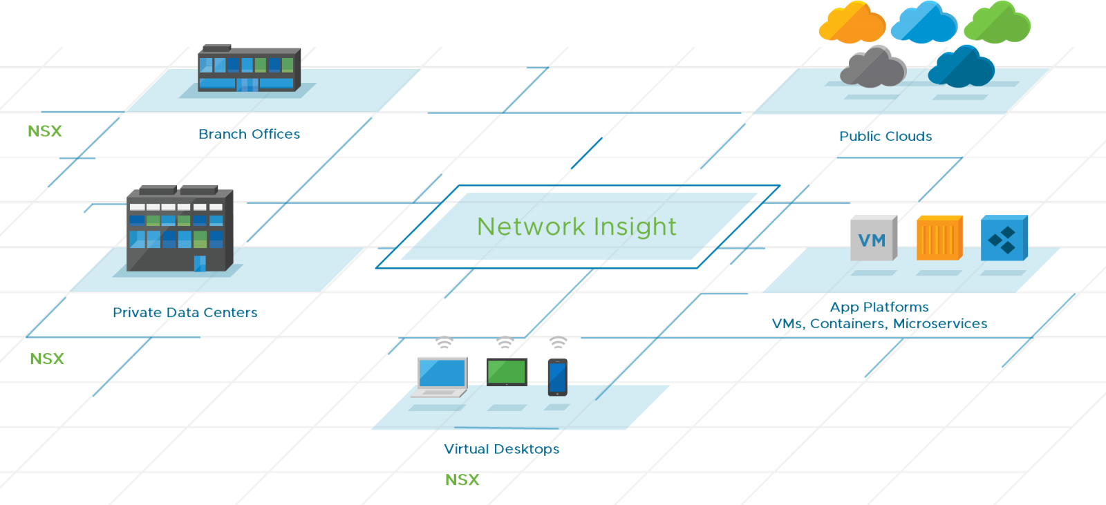
Figure 17: vRealize Network Insight Provides Vision Across the Business Fabric
vRealize Network Insight provides a complementary set of features for operationalizing adaptive micro-segmentation when combined with the Application Rule Manager tool of NSX Data Center. Figure 18 displays the five-step process to micro-segmentation:

Figure 18: The Five-Step Process to Micro-Segmentation
In addition to application and security planning, vRealize Network Insight provides an optimization and troubleshooting capability that uses multiple informational and graphical output styles of your virtual and physical networks. A third major use case of this tool is aiding in management of misconfiguration errors, NSX compliance, and scaling the NSX platform.
Supplying your toolbelt with the right set of tools in addition to the proper processes and people are the keys to a successful SDDC deployment and its operations.
2 Overview of NSX Design Using Cisco ACI as the physical fabric
This document assumes readers have a functional knowledge of NSX and Cisco ACI. Readers are strongly advised to read the following design guides for additional context; they provide a detailed characterization of NSX operations, components, design, and best practices for deploying NSX.
VMware NSX for vSphere Network Virtualization Design Guide
NSX-T Reference Design Guide
Specifically, the goal of this document is to provide guidance for running NSX over Cisco ACI as the underlay fabric. This document covers setup of the ACI fabric to meet the connectivity requirements for NSX including
- ESXi host to ACI fabric connectivity
- Standard VMkernel networking setup for an NSX design
- VLAN allocation and EPG configuration
- Overlay tunnel endpoint (TEP) configuration
- Layer 3 peering and routing configurations for north-south traffic
This design guide improves upon the earlier documentation by including explicit configuration examples of the ACI fabric. The goal in this regard is to satisfy all the NSX Data Center requirements using a network-centric setup of ACI.
2.1 Establishing NSX Data Center Connectivity Requirements
Prior to configuring the necessary objects within the ACI underlay to provide for vSphere (or the KVM transport nodes of NSX-T) and NSX communication, we must establish the connectivity requirements of an NSX Data Center deployment with ACI. That being stated, the two major requirements of NSX Data Center are essentially the same as any other underlay network:
- IP network – The NSX platform operates on any IP switch fabric.
- MTU size for Transport or Overlay – NSX requires the minimum MTU size of 1600 bytes. Application performance is optimized in an environment with a jumbo frame size setting of 9000 (a vSphere VDS maximum) across the entire fabric for operational ease.
Note: The virtualized workloads will require an MTU setting no larger than 8900 to facilitate the tunnel overlay’s additional headers.
Many environments likely use a traditional-style VLAN-backed multi-tier pod-based architecture. Whether this architecture has been chosen, or migration to a newer fabric such as the leaf-spine model, the NSX Data Center platform operates essentially the same: an agnostic but highly interoperable approach to all switch fabrics. Figure 19 highlights NSX interoperability across all switch fabrics, inclusive of one or more public clouds.
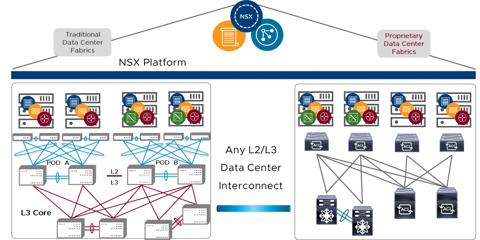
Figure 19: NSX Platform Is Interoperable upon Any Switch Fabric
The difference and the purpose for this portion of our discussion is to establish how connectivity will be provided within the ACI underlay. This begins with mapping out the logical connectivity and the vSphere PNICS that will carry this traffic.
As in our general validated design for NSX, there are four infrastructure traffic types, with one traffic type, vMotion, specifically used for vSphere ESXi clusters. Each traffic type is recommended to be run within its own VLAN. Consolidation of these traffic types into few VLANs is possible, but not recommended for this paper. Table 2 summarizes these four traffic types.
|
Infrastructure Traffic Types |
Functions |
VLAN ID |
|
Management |
ESXi and NSX management plane |
100 |
|
vMotion (vSphere ESXi only) |
VM mobility |
101 |
|
IP Storage VLAN |
Applications and infrastructure data store connectivity |
102 |
|
Transport Zone (Overlay Network) |
Overlay VTEP (NSX for vSphere) |
103 |
|
Edge Transit VLANS |
Edge Cluster Connectivity to physical underlay |
201, 202 |
|
Layer 2 Bridging |
1-to-1 mapping of VLANs bridged from overlay |
- |
Table 2: Infrastructure VMkernel Traffic Types and VLAN
Terminology: The terms Transport and Overlay are interchangeable unless otherwise noted.
These four VLANs are defined for segregating the infrastructure traffic types, or the like number of VMkernel interfaces in the case of ESXi hosts. Any logical numbering for VLANs and subnets used in the design guide are merely suggestive.
Overall, each hypervisor host will be prepared with these infrastructure networks and presented to Cisco ACI through multiple physical uplinks. In standard rack server compute format, there are usually two physical NICs. In the case of blade compute format, Cisco UCS for example, at least two logical NICs are configured to allow access to dual fabrics for redundancy and performance.
Note: For more in-depth information regarding designing NSX Data Center with Cisco UCS, see the VMworld 2017 session, Deploying NSX on a Cisco Infrastructure (NET1350BUR-r1).
During the preparation of the hosts, a special infrastructure interface for the encapsulation traffic is formulated for the express purpose of servicing the overlay traffic for the transport zone. The overlay transport zone is where the tunnel endpoints are defined that provide network connectivity within the transport zones.
NSX Data Center hosts and VM nodes (NSX-T) prepped as transport nodes create a separate kernel service to carry overlay communication. In the case of NSX for vSphere, a separate IP stack is also installed for the VTEPs. In NSX for vSphere, this additional IP stack provides a separation for the VTEPs routing table and allows use of a separate default gateway. But our design mediates the need for routing between endpoints of the respective infrastructure traffic types, by viewing the entire Cisco ACI fabric as a layer 2 domain. The Cisco ACI guides themselves state the ACI fabric can be viewed as a single layer 3 hop fabric. Therefore, there is pervasive layer 2 connectivity throughout the fabric, which allows for the four VLANs allotted for the infrastructure traffic, including the VTEPs and their transport zone, to be deployed as four flat logically separate networks. We require only a single set of these VLANs for a single NSX Data Center deployment to segregate the infrastructure traffic.
To provide allowed connectivity between endpoints of each individual traffic type, we will use an ACI construct called an endpoint group (EPG). In ACI, all endpoints within an EPG are permitted to communicate without additional allowances, filters, or contracts. Each of the infrastructure VLANs will be mapped to an individual EPG. In this use of VLANs in ACI, the corresponding configuration step involved in their use when mapping endpoints to EPGs is one of several fundamental management concepts for managing connectivity within the ACI fabric. The optimal design option for EPG use in our design is “EPG as a VLAN.” We will show how to configure the use of EPGs and all other necessary Cisco ACI constructs required for our NSX Data Center deployment on a Cisco ACI underlay.
Our design will make use of a network-centric deployment of ACI to remove much of the complexity involved in its setup and day-2 operations. This essentially means all connectivity to the fabric is configured in separately assigned VLANs through each EPG. For the rest of the design, the VLANs required for NSX are equivalent to an EPG required to be configured at an ACI leaf through a combination of fabric policies and tenant-based Application Profile EPGs. Figure 20 displays the allowance of intra-EPG communication, with no communication permitted inter-EPG without an ACI contract.
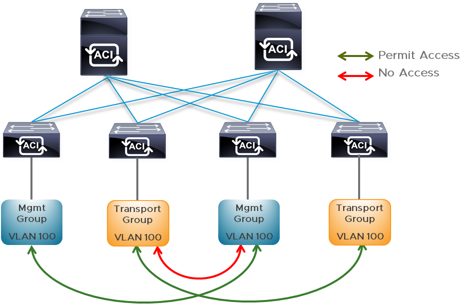
Figure 20: ACI Intra-EPG and Inter-EPG Communication Example
Refer to the following for more information on using EPG as VLAN:
- EPG as a VLAN section in Cisco Application Centric Infrastructure (ACI) – Endpoint Groups (EPG) Usage and Design
- Per Port VLAN section of Cisco Application Centric Infrastructure Fundamentals
In using an EPG as a VLAN, a network-centric operational construction of the ACI fabric helps establish a good portion of the required communication for our NSX on ACI Underlay design. Figure 21 displays a high-level view of NSX Data Center running on an ACI infrastructure. Pictured are the three standard NSX operational clusters: Management, Compute, and Edge. In addition, the associated infrastructure connectivity for the NSX operational clusters is managed through Cisco ACI EPGs. Figure 21 also includes the required EPGs for the transit communication use by the NSX edges to route the NSX overlay network.
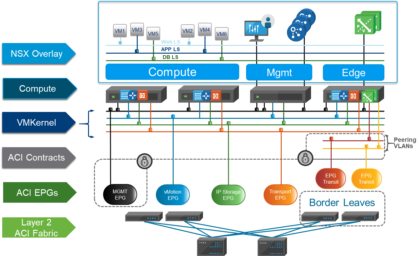
Figure 21: NSX Data Center Deployed on an ACI Underlay – High-Level EPG View
Configuring the infrastructure EPGs (VLANs) is a one-time task in the ACI APIC and provides the basis for deployment of NSX and the NSX platform operation. With ACI operating as a layer 2 fabric for the bulk of the infrastructure communication, the infrastructure EPGs can be scaled by adding physical ports along with any newly introduced switches when additional compute growth is required. This design ideal was created with the explicit purpose of aiding the maintenance of a stable switch fabric operating state, especially Cisco ACI. A minimal amount of modification to the fabric’s basic transport configuration is required when future scale-out is required. Our design facilitates the creation of NSX logical networks independent of the physical network and therefore eliminates defining new EPGs (VLANs) for new logical segments, additional workloads, or any logical application-scaling requirement needed for workloads deployed within the NSX overlays.
For all virtual workload traffic, the NSX Transport VLAN is used. For example, all VMs deployed upon the logical overlay use a default gateway represented as a logical interface (LIF) of a distributed logical router (DLR) shown previously in the section on Distributed Routing. This logical switched and routed fabric operates independent of the switch fabric for the most part.
Likewise, the infrustructure VLANs for any necessary routed physical fabric connectivity may use the distributed gateway feature of ACI. This ACI feature provides a consistent routed interface for the entire infrastructure network on every ACI leaf if needed. The key understanding is that the default gateway of the VM is provided by NSX and is different than the gateway for the VMkernel interfaces.
As previously noted in Table 2, there are additional VLANs required to establish the transit communication paths used for the edge cluster’s connectivity to the physical fabric. Cisco ACI has a specially designed EPG called an L3Out to establish routed connectivity external to the fabric. An ACI external routing domain is a specific portion of the ACI tenant connectivity for routed connectivity exiting the ACI fabric. Our design makes use of this ACI abstraction along with a minimum of two transit VLANs configured for the L3Out EPG.
An optional set of VLANs may also be required if leveraging NSX Data Center for L2 bridging. Table 2 references that the VLANs required for this use will be equivalent to the number of overlay networks (for example, VXLAN IDs to VLAN IDs) bridged to VLANs in the physical switched network.
2.2 Cluster Connectivity for the NSX Infrastructure Clusters
The general design criteria used for connecting ESXi hosts (KVM hosts for NSX-T) to the ToR switches for each type of rack takes into consideration
- The type of traffic carried – Overlay, vMotion, management, storage
- Type of isolation required based on traffic SLA – Dedicated uplinks (for example, for vMotion/Management) vs. shared uplinks
- Type of cluster – Compute workloads, edge, and management either with or without storage
- The amount of bandwidth required for overlay traffic (single vs. multiple VTEP/TEP)
- Simplicity of configuration – LACP vs. non-LACP
- Convergence and uplink utilization factors – Flow-based vs. MAC-based
A diverse setup of uplink connectivity options is provided by the respective NSX Data Center platforms (NSX for vSphere and NSX-T), and their respective hosts’ uplink and virtual switching service offerings. For connectivity discussions in this document, all hosts used will be assumed to be dual connected to the switch fabric. Further connectivity discussion and guidance can be found within their respective NSX Data Center design guides.sda
2.2.1 Management Cluster Connectivity
The management cluster consists of hosts supporting multiple critical virtual machines and virtual appliances. The VMs for the NSX manager and controllers are typically deployed in the management cluster requiring high availability (for surviving the failure of the host or ToR/uplink). Further, the management cluster is not required to be prepared for use with an overlay, as management connectivity is performed via the fabric underlay. Thus, connectivity for the vSphere hosts forming the management cluster is a VLAN based port-group on a separate VDS from the other functional clusters, Compute and Management.
This document calls out the use of SRC_ID for all teaming of the uplinks from the virtual switch perspective. LACP teaming mode can be used and would require LACP on the Cisco ACI for the ports connecting to the management hosts. For Cisco ACI switches, this is achieved by enabling traditional layer 2 VLAN-based vPC (Virtual Port Channel). To avoid the necessity for additional PNICS and uplink connectivity, all the traffic types including management, vMotion, and IP storage can be configured to use the same LAG. This would require a substantial change in the initial configuration of the fabric access policies to assemble the necessary ACI objects to support vPC connectivity. Consult Cisco ACI documentation for use and configuration of vPC.
2.2.2 Compute Cluster Connectivity
NSX offers a clear departure from the traditional methods for designing the infrastructure connectivity. The necessary VLANs are required to be defined only once for infrastructure traffic (overlay, vMotion, storage, management). Connectivity for the logical switching of the overlay for the virtual workloads, VMs, and containers are defined programmatically without relying on the physical network. This decoupling enables a repeatable rack design where physical planning (power, space, cooling, and cookie-cutter switch configuration) is streamlined. The physical network only requires robust forwarding and adequate bandwidth planning.
The compute cluster requires the most flexibility as it carries multiple types of traffic. Each type of traffic can have its own service level. For example, the storage traffic requires the lowest latency, as opposed to vMotion, which may require higher bandwidth.
Some workloads may have many sources and destinations and require load sharing by using multiple tunnel endpoints (VTEPs or TEPs). The flexibility of selecting teaming mode per infrastructure traffic type, and allowing variability in choosing the teaming mode for the overlay (as described in the VDS uplink configuration section), are primary reasons for not recommending LACP for the compute cluster host’s connectivity to Cisco ACI. An additional reason that is a corollary consideration is the day-2 operational concern: simplifying troubleshooting.
2.2.3 Edge Cluster Connectivity
NSX Data Center edges provide multi-function services such as north-south routing, firewall, NAT, load balancing, and various VPN capabilities. The capabilities and features are beyond the scope of this paper. Please refer to the individual design guides for the respective NSX Data Center platform:
- VMware NSX for vSphere Network Virtualization Design Guide
- VMware NSX-T for Data Center Reference Design Guide
This document covers the necessary technical details pertinent to physical and logical connectivity required for connecting an NSX Data Center edge cluster to the switch fabric. The critical functions of the edge cluster that provide connectivity to the NSX Data Center overlay are
- On-ramp and off-ramp connectivity to physical networks (north-south L3 routing delivered by NSX Edge virtual appliances, or NSX bare metal edge of NSX-T for Data Center)
- Allows communication with physical devices connected to VLANs in the physical networks
- Supports centralized logical or physical services (firewall, load balancers, and logical router control VM)
NSX edges perform a similar function as border leaves, providing on-ramp and off-ramp gateways just like ACI connected resources do, to access northbound networks and users. It is highly recommended that you align the NSX Edge cluster connectivity to border leaves in the ACI fabric.
The benefits of confining edge clusters to the pair of border leaves within ACI are
- Consistent single-hop connectivity for the traffic flow from NSX to ACI connected devices as well as north-bound network access
- Localizes the routing configuration for north-south traffic, reducing the need to apply any additional configuration knobs for north-south routing on the compute leaves
- Allows network admins to manage the cluster workload that is network-centric (operational management, BW monitoring, and enabling network-centric features such as NetFlow and security)
This is typical of any spine/leaf design to use border leaves.
2.2.4 Demystifying the Overlay Transport and IP Connectivity
This section demystifies the use of an overlay, its capabilities, and the difference in the way ACI implements the physical underlay functionality. It also helps to understand the benefits of using an overlay encapsulation originating from a hypervisor, such as an ESXi host to support logical networks and layer 3 logical routing, that are agnostic to the physical network underlay. Also note that any encapsulation used by NSX, VXLAN for NSX for vSphere, or Geneve for NSX-T provide the exact same overlay benefits proposed in this discussion.
NSX for vSphere for Data Center enables standard VXLAN encapsulation, as does the proposed Geneve in the case of NSX-T for Data Center, at the hypervisor level and thus treats the ACI iVXLAN fabric like any other IP transport. The advantage of overlay encapsulation in the hypervisor follows.
An overlay encapsulation sourced in the hypervisor decouples the connectivity for the logical space from the physical network infrastructure. Devices connected to the logical networks can leverage the complete set of network services (load balancer, firewall, NAT) independent from the underlying physical infrastructure. This solves many of the challenges within traditional data center deployments, such as the risk of L2 loops being diminished, agile and programmatic application deployment, vMotion across layer 3 boundaries, and multi-tenancy support. It also overcomes the VLAN limitation of 4,094 logical segments.
Hypervisor-based encapsulation allows NSX to not only operate on a proprietary fabric like ACI, but also allows the freedom to change or enhance the encapsulation since it is done in software. Decoupling the underlay from the overlay further enhances network operations and allows faster adaptation of technology.
Traffic flow for an NSX overlay on a Cisco ACI fabric is treated similarly to any other switch fabric from an application workload viewpoint. The Cisco ACI fabric is not aware of the NSX overlay encapsulated traffic and treats the traffic received from the tunnel endpoints as normal IP traffic. The ACI fabric forwards all communication within the switch fabric using its own non-standard proprietary VXLAN header for inter-rack traffic, with the ACI span of control terminating at the top of rack as a VLAN.
The following steps are the high-level overview of a packet processed for end-to-end communication of a VM-to-VM workload using an NSX for vSphere deployment with an ACI fabric underlay. Figure 22 provides a graphical view of the same set of steps that are discussed.

Figure 22: NSX VM-to-VM Packet Flow over an ACI Underlay
- Source VM originates an L2 Frame encapsulating an IP packet with source and destination IP address for the application workload.
- Source hypervisor performs lookup for a VTEP where the destination VM is hosted. The VM’s L2 frame is encapsulated with the corresponding VXLAN and UDP header. Further, the outer frame constructed will contain source and destination IP addresses of the NSX VTEPs and an 801q VLAN value for the NSX for vSphere transport zone.
(Up to this point, these steps follow a standardized method used for NSX overlay packet processing and forwarding.)
- When this standard VXLAN frame from the hypervisor reaches the ACI leaf, the ACI leaf will remove the outer VLAN encapsulating the NSX VXLAN packet and add its own non-standard, proprietary VXLAN header used for ACI tunnel endpoint communication within the ACI switch fabric.
(This will look like a “double encapsulated” packet if sniffed inside the fabric; more on this shortly.)
As the packet egresses the ACI fabric, the ACI leaf will strip the ACI fabric VXLAN encapsulation and replace it with an appropriate destination VLAN header, leaving the original NSX VXLAN packet intact.
- The destination hypervisor will strip off the VLAN header after transferring it to the appropriate VTEP dvPortgroup. The VTEP will receive this packet, strip off the NSX VXLAN header, and transmit the packet onto the NSX logical switch where the destination VM resides.
- The destination VM receives the intended L2 frame.
This encapsulation process is like the packet flow used by any standard VLAN-backed switch fabric that only modestly differs in the ACI fabric use of VXLAN. Also, an NSX-T overlay would employ the same general set of steps. Regardless of the fabric’s use of either encapsulation, VLAN or VXLAN, packet forwarding on an NSX platform is performed at line rate.
To complete this discussion, the previously mentioned “double encapsulation” has zero effect on the ability to provide proper flow monitoring or packet analysis. Any modern packet analysis tool can decode the headers of packets captured within a VXLAN underlay with NSX VXLAN running on top. Figure 23 displays an example of a captured packet within the ACI fabric using ACI ERSPAN to forward packets to an analysis system. A VM running a recent version of Wireshark displays a decoded NSX VXLAN packet.

Figure 23: Wireshark Decoding NSX VXLAN Packet Captured on an ACI Underlay
The use of an NSX overlay is quite formidable. Use of NSX overlays provides the foundation for a truly software-programmable network that leaves the hardware infrastructure untouched, simplifying its operation and maintenance while only requiring a small and stable set of VLANs for the infrastructure traffic.
2.3 Cisco ACI Connectivity Options with the NSX Infrastructure
Our standard NSX design calls out three options for deployment of the compute services:
- Three separate functional compute clusters consisting of Management, Compute, and the Edge cluster
- Collapsed Management and Edge cluster and a separate Compute cluster
- Collapsed Management, Compute, and Edge deployment
The last two options may be employed for smaller deployments, operational necessity, or a desire for simplicity. The initial option, separating all three, tends to be chosen for mid-size to larger deployments. This guide concentrates much of its discussion on either one of the first two options. Nevertheless, most design variations regarding this section, interfacing the compute services with the ACI infrastructure, are concerned with the number of PNICS used for a rack server infrastructure platform, and which type of teaming should be used for load distribution and availability. The blade server form factor, such as Cisco UCS, would have a different set of connectivity options to use.
Note: For a discussion on connectivity with NSX and using the Cisco UCS blade form factor, review the VMworld presentation from 2017, Deploying NSX on a Cisco Infrastructure (NET1350BUR-r1). Also, the previously mentioned design guides for NSX Data Center for vSphere and for NSX-T should be referenced for a discussion on load sharing.
This design guide will use the VMware recommendation for active/active links for connectivity between the hosts and the physical switches whenever possible and avoid use of proprietary switch fabric LAGs. This would mean use Route based on the Originating virtual port for vSphere. A variety of failover connectivity options are recommended for KVM transport hosts with NSX-T. These recommendations avoid Cisco vPC (Virtual Port Channel). This recommendation is based upon the highest level of availability, low latent multi-uplink utilization for the most part, along with simpler day-2 operations for the least complexity. In no way does this imply Cisco vPC or any other vendor’s proprietary multi-etherchannel LAG is unsupported. Our concern is performance and smoother operations.
The design will bind the appropriate infrastructure VLANs described in Table 2 (Section 3.1). Each of these will require a separate EPG with its own bridge domain within a single ACI tenant container. This correlates to our standard requirement of a separate VLAN on any non-ACI network fabric for each infrastructure traffic type. Treating the entire fabric as a layer 2 switch domain will mean that the infrastructure networks will use a single subnet. This subnet should be sized accordingly to maximize the deployment and its future growth. Therefore, a network prefix with a /22 mask is chosen for the infrastructure networks in this guide for these reasons.
Note: Sizing the infrastructure networks is based on the current largest validated configuration maximums. Future validated configuration maximums may warrant use of a larger network prefix to provide room for scaling the deployment.
Sizing the subnets for the application deployments calls for further consideration for the type of deployment topology desired, such as flat or network tiered. Also, when applications are entirely virtualized, all routing will occur within the NSX layer. In most cases, this means there is no need for routing of the application tiers to be performed by the underlay. For all virtual workload traffic deployed within an NSX overlay, the distributed routing component of NSX will be the L3 gateway.
A final consideration for interconnectivity is where the NSX overlay intersects with the physical network. With any underlay, including ACI, routing interoperability with the underlay is required where NSX edges peer with their respective L3 neighbors. For ACI, the NSX edges will peer with the ACI border leaves using ECMP routing connectivity. The network subnet sizing chosen for these transit networks used for edge ECMP connectivity should be sized according to future growth needs. Use of the edge cluster has been previously outlined. For further discussion of edge cluster and edge ECMP connectivity with the ACI border leaves, see Configuring ACI Border Leaves Connectivity.
3 Configuring Cisco ACI for an NSX Data Center Deployment
Designing and configuring any underlay for preparation for an NSX platform deployment is an important process. The switch fabric operational requirements are reduced extensively by implementing network virtualization designs for NSX Data Center. VMware NSX Data Center: Accelerating the Business discusses this idea extensively. Therefore, the goal of this document is to substantially reduce the operational complexity of an ACI underlay. Many of the proprietary nuances introduced by ACI may add to the deployment time frames. There is extensive planning required to ensure an appropriate use of the ACI fabric and avoid the usual set of pitfalls:
- Extraneous use of filters that overfill the TCAMs of the ACI leaves for only a limited number of applications.
- Complex operational models using a legacy model of network stitching or forcing packet flow through “concrete” firewalls, polarizing traffic at specific edge leaves.
- Complicated multi-site topologies involving multiple complex protocol mixes along with required non-standardized protocols.
- Design models that consistently require the latest switch model as the minimum hardware switch model for key elements of the fabric.
- Cloud models with disjointed operational models with the hardware-defined models of the on-premises deployments.
- Inserting non-native and unsupported services (Cisco ACI VMM) within the ESXi hypervisor resulting in more operational overhead, all to achieve what is natively provided by the NSX Data Center platform on vSphere.
- Numerous historic enterprise data center problems plaguing legacy hardware-dependent schemes, including hardware churn, differences in troubleshooting and monitoring operations dependent upon heterogenous hardware switch platforms that accrue over time, and no cloud-like model offering the same operational or troubleshooting model for the desired policy.
VMware has architected and successfully implemented a modern advanced design involving less operational overhead when preparing the ACI underlay for VMware NSX. This document applies the same highly interoperable approach to the underlay as we would for any automated switch underlay. The design normalizes many of the proprietary fabric requirements of Cisco ACI so that scaling the underlay involves the least amount of effort for switch fabric management. More effort can be placed on deploying and scaling applications with a complete software-defined approach, whereby all application service needs, micro-segmentation security, load balancing, IPAM, and NAT scale respective to the programmatic virtualized network.
3.1 Initial ACI Fabric Setup
The ACI fabric is assumed to be initialized and set up with multiple leaves and a minimum of two spines. Use Cisco ACI guides for initializing the ACI fabric. Ensure at the end of the setup there are also three APIC controllers configured for the ACI management plane. A single controller is acceptable for PoCs and labs but not for production.
The following items are also required or recommended for setup for Cisco ACI to operate sufficiently. The initial setup list is not exhaustive but includes the following considerations:
- Jumbo frames (9 K MTU) as VDS supports a maximum of 9 K MTU (default setting for the ACI fabric)
- Out-of-band and/or inband management setup for the ACI fabric
- DNS
- NTP
- SNMP logging
- Single pod and zone (default)
- Data center connectivity (northbound) – This guide will not cover that connectivity as requirements and customer needs for this connectivity will vary.
Note: The initial setup list is offered as a recommended list for prerequisites that most switch fabric operations would use, and in most cases, need. This guide does not make any recommendations for these items. Settings for these features are specific to the customer needs on how the infrastructure is to be managed and operationalized.
For help on the initial setup for the ACI underlay, the Cisco APIC Getting Started Guides, Release <x.x>, referencing the specific ACI release in use, can be found in the Cisco Application Policy Infrastructure Controller documentation library.
The assumption is two ACI leaves have been discovered, initialized, set up, and are ready to accept configuration for connectivity to the NSX operational clusters (Management, Compute, and Edge) at the end of the setup process.
This guide will divide the remaining setup of the ACI fabric into configuring the general fabric objects, or Fabric Access Policies, and the more specific configuration of the ACI tenant object containing the NSX deployment. The fabric policies and access policies are used by ACI to provide feature enablement, protocol setup, and guidelines for use and generalized service operation. The ACI tenant object provides a network-centric container for a specific set of Application Policies for a unit of business or in the case of our NSX design, a simplified deployment environment. An ACI tenant will be leveraged for the necessary EPGs used for the NSX infrastructure connectivity, layer 2 bridging, and layer 3 external connectivity.
Note: This “ACI Tenant” references the ACI tenant container abstraction. Tenancy of ACI is more network-centric. Currently, NSX provides tenancy at a virtual level and is orthogonal to the ACI tenancy concept, and does not necessarily need a 1:1 mapping to the ACI Tenant container. NSX offers various features conducive to tenancy servicing. Security groupings or separate edge instances with or without NAT and other virtual abstractions can be combined to formulate a tenant-based function. Also, for virtual network isolation for strict multi-tenancy, it is possible to map VRF-based tenancy to NSX logical separation. For most deployments, this is not necessary, so deployment is simplified.
Application deployment can leverage VMware NSX deployment ideals, which will not require additional ACI “Tenant” abstractions. This speeds deployment of the underlay and alleviates rigid complexity for fixed configurations of ACI tenants, and enhances operational agility. See Section 3.3, Configuring theh NSX on ACI Fabric Tenant, for more specific information on this portion of the setup.
Note: The path, use or nonuse of wizards, and the order of ACI object creation was chosen specifically due to the dependency requirements of later objects to be created. The goal is to provide as emphatically possible all objects that are necessary, and their representational use and purpose in the infrastructure design. A further goal is to reduce the overlapping nature of object creation and the serial dependency on one or more objects if using many of the available wizards within the APIC of ACI.
3.2 Configuring the Fabric Access Policies for NSX and Hypervisor (vSphere and KVM) Connectivity
Cisco ACI uses Fabric Access Policies to prepare and configure the leaf switches and their server-facing interfaces for connectivity, and in this case the NSX host clusters. A series of objects are required to complete the necessary set of abstractions and settings for the NSX compute cluster attachment. ACI does include a wizard labeled in the APIC UI interface as “Configure an interface, PC, and VPC” wizard. It is recommended to not use this wizard as it may create an incomplete set of the necessary objects our design recommends. In addition, the wizard does not allow you to customize the naming of all the objects instantiated by the wizard. The wizards tend to disguise the number of objects created and their serial dependencies. This can lead to confusion later on if troubleshooting a problem related to a specific set of the ACI objects and their dependent objects. Although ACI’s interface does provide a means for discovering an objects dependency and uses, it is not easy to discern the effects a change will have upon the serially aligned set of dependent abstractions and avoid a harmful domino effect.
Note: Most ACI objects cannot be renamed. It is best in many instances to name objects directly when possible and provide a description of their use. ACI objects can leverage the use of “tags” to help align an object’s function. If there is a desire to rename an object, a scripted process of deleting and recreating the objects with a different name will be required in most cases.
We recommend configuring the ACI abstractions either directly or through the ACI API for the objects called out for this design. Several ACI object abstractions will still be instantiated due to dependencies upon creation of a related “parent” of said dependent object. Figure 24 outlines the objects used by this design and their relative dependency or association within the ACI fabric policies.

Figure 24: NSX on ACI Fabric Access Policy Object Reference
Note on ACI graphic images: All references for ACI objects to be created are done so within the ACI APIC UI for the purposes of this document. Naming of ACI objects has strict rules, therefore names used for the ACI abstractions in this document are indicative of purpose as opposed to specific naming suggestions.
3.2.1 Creating the Fabric VLANs
There are several different objects that could be the initial object for creation with the Cisco ACI APIC. This guide will start with the most basic, the VLAN pools. This guide recommends creating two VLAN pools: one for the infrastructure connectivity, and the other VLAN pool for the external layer 3 transit connectivity of the NSX edges. This latter pool, for the layer 3 external connectivity, could include the VLANs also used for the north side or data center core interconnectivity. Larger environments may have an operational desire to create separate pools for each functional use.
VLAN pools will be later associated to ACI Domain objects and instantiated for use on switch interfaces through an ACI fabric access policy object called the Attachable Access Entity Profile Object (AEP). The VLAN pool objects are discussed within this section of the document whereas the ACI Domain and ACI fabric access policy objects are discussed in later sections.
These VLAN pool objects are created under the Pools node within the Fabric Access Policies of the ACI APIC:
- NSX Infrastructure Pool – This pool is used for the four infrastructure networks: Management, IP Storage (if necessary), vMotion (vSphere specific), and the transport network. For instance, for the vSphere ESXi hosts, these VLANs will be used for the 802.1q encapsulated traffic between the compute infrastructure’s VMkernel interfaces, inclusive of the tunnel endpoints (VTEPs and TEPs), and the ACI leaves.
- NSX External Transit VLAN Pool – This pool is used for the NSX Edge Transit VLAN connectivity and may also pull double duty with additional VLANs used for the ACI data center connectivity.
Figure 25 and Figure 26 display the two pools created to encapsulate traffic between the ESXi hosts and the ACI fabric for infrastructure and external connectivity.
|
VLAN range for an “Infrastructure pool” for a single NSX on ACI deployment requires only four VLANs. If more deployments are planned or there is a need for multiple infrastructure networks per infrastructure resource, additional VLAN ranges can be added to this object. |

Figure 25: NSX Infrastructure VLAN Pool
|
VLAN range for an “External pool” for a single NSX on ACI deployment requires only two VLANs for the external transit connectivity. If more deployments are planned or there is a need for multiple external networks for additional external connectivity, additional VLAN ranges can be added to this object. |

Figure 26: NSX External VLAN Pool
Following Cisco ACI best practices, each of the pools are created to encompass a plausible future use of VLANS greater than the initial need of only four VLANS for the infrastructure and a few for encapsulation of the external connectivity. Remember, ACI VLAN pools cannot be removed or modified if respective VLANS of the pools are in use without disrupting traffic. This would be the same as any change of the VLANS when using standardized switch hardware. The VLAN pools, if necessary, can be appended with additional VLAN ranges when the need arises.
Note: If there is a need to repurpose any VLAN within the range that is used, the entire VLAN range would have to be withdrawn from use, deleted, and a new “VLAN range” created. It may be more prudent to add each VLAN value individually, and avoid the use of the “range” to allow future adds and deletions more easily.
3.2.2 Creating the Fabric Domains
Next up will be the creation of the ACI Physical and External Domain objects. Domain objects describe how a device is connected to the fabric. A physical domain object represents an internal infrastructure location for bare metal or network-centric attachment for this design. An external domain, more specifically an external routing domain, denotes infrastructure device attachment to external layer 3 routing. This design calls out the use of one physical domain and separate external domains.
One physical domain references the attachment of the NSX Infrastructure clusters (Management, Compute), and the east-to-west logical traffic the Edge cluster interconnects to the ACI fabric leaves.
For the external domains, the design will use two for operational simplicity. One external domain references the connectivity for the NSX Edge infrastructure’s north-south routing with the ACI fabric. The other external domain will be used to reference ACI northbound connectivity toward the data center core. This connectivity is not discussed in this document and it is left to the customer to determine its configuration.
The physical and external domains are also created under the Fabric Access Policies of the APIC. When creating the domains, select the corresponding VLAN pool. The Attachable Access Entity Profiles (AEPs) referenced within the domain object interface can be created now or later and associated to their domain object at that time. Figure 27 displays the dialogue window for creating the physical domain.

Figure 27: NSX Physical Domain
Figure 28 and Figure 29 display the dialogue windows for creating each of the two external domains.

Figure 28: NSX L3 Domain for the Edge Cluster Connectivity

Figure 29: ACI Fabric L3 External Domain for the Data Center Core Connectivity
As noted earlier, the physical domain identifies the specific connectivity locality of the functional NSX vSphere clusters. Figure 30 details the use of the domains and the VLAN pools that are to be created and mapped for their corresponding uses.
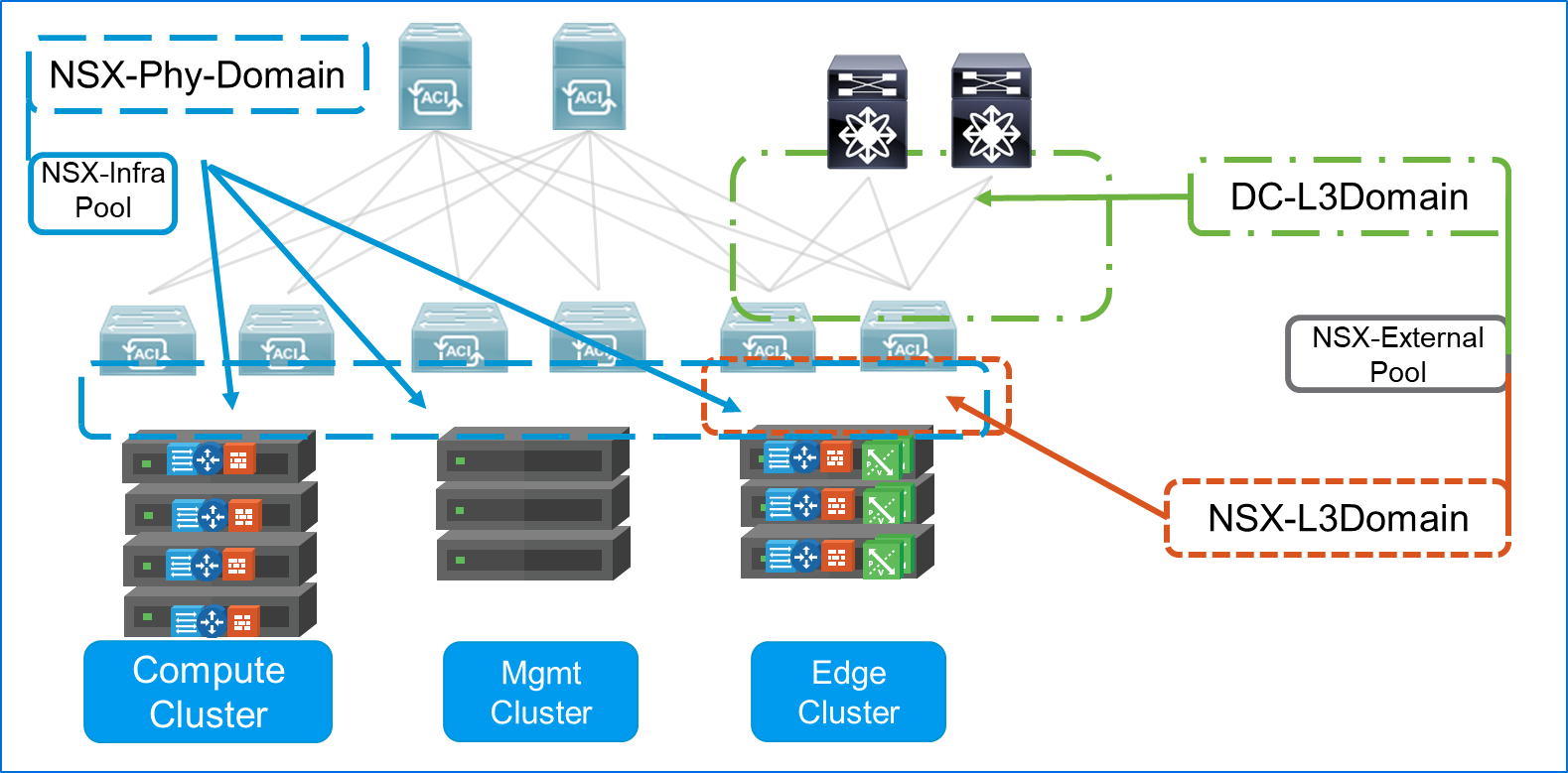
Figure 30: Domains and VLAN Pool Use. The NSX-External Pool Can Be One Pool (As Shown).
Note: Figure 30 displays an overlap of NSX-Phy-Domain and the NSX-L3Domain where the Edge cluster connects to the ACI fabric. Remember, the Edge cluster also participates in the connectivity for the NSX overlay and thus requires connectivity for the infrastructure as well as the external network. This may in many cases be the same two physical uplinks when a rack server platform is used for the Edge cluster.
Additional note: Figure 30 could easily simulate a combined Management and Edge cluster by eliminating the separate Management cluster and combining the functional services of management and edge into a single cluster. Configuration of the ACI fabric and objects discussed will be identical, with one exception: Fewer switch ports will be required for use when attaching the individual bare metal hosts in a later configuration step.
3.2.3 Creating the Interface Policy Objects
Cisco ACI uses Interface Policy objects to define the switch protocols enabled and their respective configuration. This design will recommend the use of LLDP or CDP to be used on switch fabric interfaces connecting to the hypervisor hosts. This design calls for one or both protocols to promote easier troubleshooting of switch-to-host connectivity. There is a substantial list of other protocols and features that ACI leaves support, such as BFD, Spanning-tree, MisCabling protocol, Storm control, and Port Security; but these are not required. Individual organizational topology needs may necessitate their setup and use. The respective LLDP and CDP are configured under the Interface Policies of the Fabric Access Policies. Figure 31 displays the creation of an LLDP Interface Policy.
Figure 31: Creating an LLDP Interface Policy
Note: Coordinate system and virtualization teams with the network team to decide which protocol(s) should be configured.
3.2.4 Create the Attachable Access Entity Profile Object
After creating the Interface Policy objects, you have an Attachable Access Entity Profile (AEP). This abstraction defines the “where” of the fabric configuration. It begins to do this by assigning the domain profiles of the fabric policies to the AEP object for later association with the Leaf Access Port Policy Group object. Recall that the domain profiles also have the VLAN pools associated to their object. VLANs from these pools will later be used when assigning the interfaces to the EPGs created in the NSX tenant for ACI.
The AEP is created under the Global Policies of the Cisco ACI APIC Fabric Access Policies. Associate only the NSX-Physical and NSX-L3Domain domains. Figure 32 displays the creation of the AEP with the required association of the physical domain and the L3 external domain used for routing the NSX overlay into the ACI fabric leaves. An additional AEP can be used to associate the L3 external domain for the data center core connectivity.

Figure 32: Creating the Attachable Access Entity Profile (AEP) and Associating the Domains
This completes the creation of the AEP object as it will be associated to the interfaces in a later step.
3.2.5 Creating the Leaf Policy Group Object
The Interface Policy objects for setting the port policies for CDP, LLDP, and any other desired interface protocol settings are required to be associated to the AEP using the Leaf Access Port Policy Group object. This is the initial step to associate these switch interface protocol policies to switch interfaces in a later step. The Leaf Access Port Policy Group object is created beneath the Leaf Policy Group node under the Interface Policies of the Fabric Access Policies. This object will associate the LLDP Policy object and the AEP object previously created. Figure 33 displays the dialogue window to create the Leaf Access Port Policy Group object.

Figure 33: Create Leaf Access Port Policy Group Object
As stated earlier in the design guide, the design is only calling out the necessity for the LLDP Policy (or CDP Policy) to aid in troubleshooting connectivity. Other L2 and Interface Policies for the interfaces and switch fabric can be used and associated when creating the Leaf Access Port Policy Group object. The need for other protocols and features will be dependent upon the individual needs of each deployment.
All that is necessary here is to name the object and select the previously created LLDP policy and AEP objects for their respective options.
3.2.6 Creating the Leaf Interface Profile
Next, ACI uses the Leaf Interface Profile object to associate the previously created Interface Policies (LLDP and/or CDP in this design) and AEP to a specific set of interface IDs with an Interface Selector object called the Access Port Selector object. The Access Port Selector object created here will later be associated to a Switch Profile object to identify the fabric leaf switches associated to the Interface Policies. Figure 34 displays the logical object associations.
The Leaf Interface Profile is created under the Leaf Profiles node of the Interface Policies. The Leaf Interface Profile object will require a name in addition to creating the Interface Selector or Access Port Selector object.

Figure 34: Beginning the Creation of the Leaf Interface Policy Object
When creating the Access Port Selector object, assign the appropriate interfaces of the ACI leaves providing direct connectivity to the NSX hosts used in the deployment of the NSX functional clusters: Management, Compute, and Edge. Figure 35 displays the creation of the Access Port Selector object, the assignment of ACI Leaf interface identities, and the association to the previously created Interface Policy Group object.
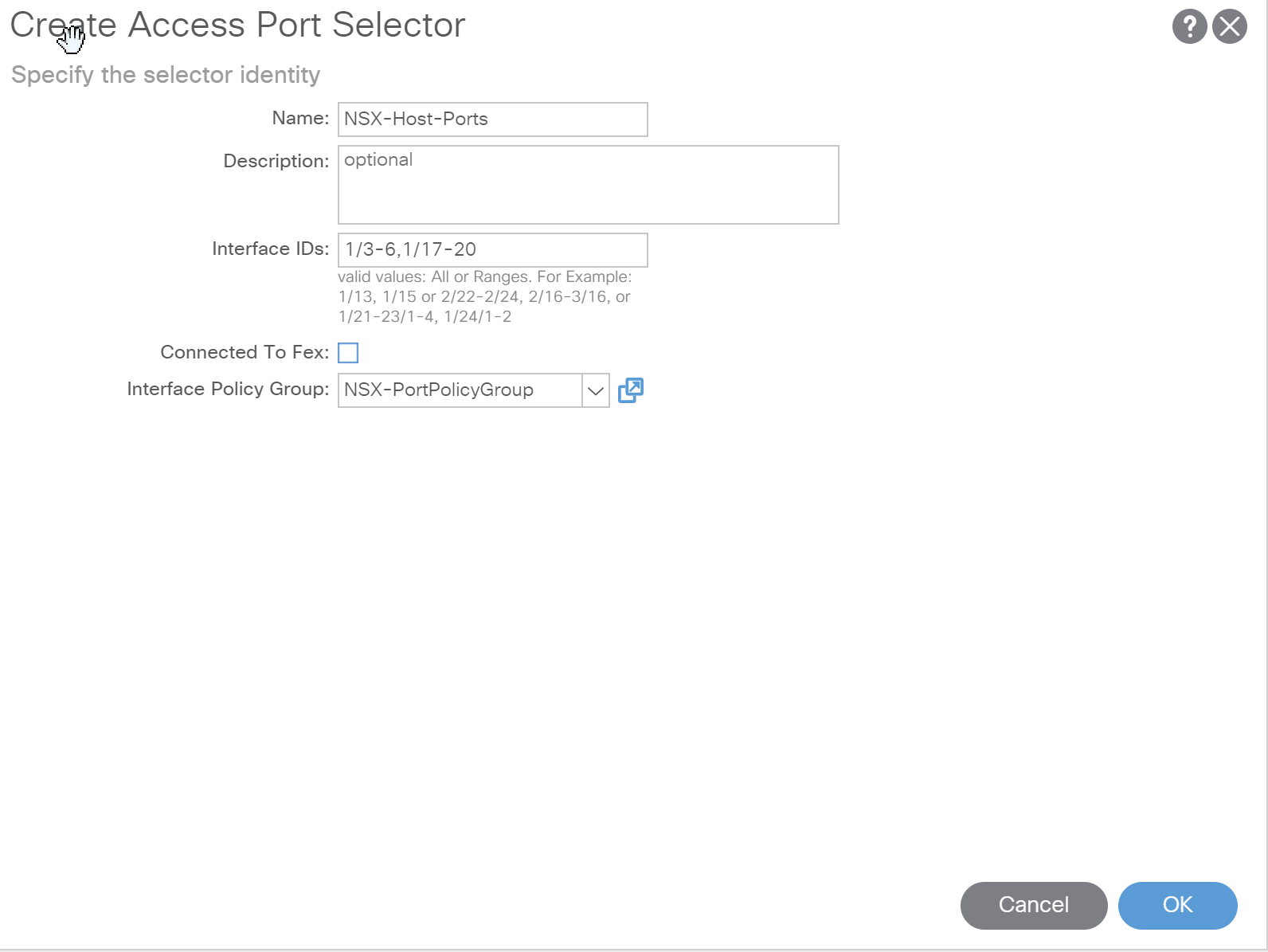
Figure 35: Creating the Access Port Selector Object of the Leaf Interface Policy Object
Figure 36 displays the completed Leaf Interface Policy object. The ACI interface IDs and the Interface Policy Group object information are now associated.

Figure 36: Completing the Leaf Interface Profile Object
Cisco ACI still requires a few more objects to bind these configured policies to specific fabric leaves or switches and associate use of the specified interfaces.
3.2.7 Creating the ACI Leaf Profile Object
The final set of Fabric Access objects at this stage of the design involves the creation of the Leaf Profile object of the Switch Policies. This object identifies which ACI fabric leaves will be associated to the previously created Leaf Interface Profile along with any Switch Policy Group objects. Switch Policies and Switch Policy Group objects define protocol policies globally to the individual switches.
Recall that the Leaf Interface Profile identifies the switch interfaces with a dependent Access Port Selector object. Associating the Switch Policy/Leaf Profile to the Leaf Interface Profile combines the configured interface IDs with the switch leaf IDs. The ACI fabric will now have the properly configured interfaces on specific fabric leaves for use in the design.
The Leaf Profile object is created beneath the Profiles node of the Switch Policies, as shown in Figure 37. You will be required to assign a name to the Leaf Profile. Add a Leaf Selector object to identify the switch IDs and create or associate a Switch Policy Group object. It is optional to configure a (Switch) Policy Group object and associate it to the Leaf Selector. The Switch Policy Group object is optional and only required to modify default switch operations and protocol settings. The NSX on ACI underlay design does not require additional protocol settings for the switches.

Figure 37: Initial Dialogue Window of the Leaf Profile
After completing the Leaf Selector configuration and optional Switch Policy Group object creation and assignment, there is the option to create a Switch Module Selector Profile, as shown in Figure 38. You create any of the “Module” objects when necessary. The document assumes the use of fixed-chassis models for leaves.

Figure 38: Completing the Leaf Profile by Adding the Interface Selector Profile
This should complete the creation of the Leaf Profile object. At this point, there are no more required Fabric or Fabric Access Policies for the design. The next step is to begin building the NSX-On-ACI Tenant configuration in the ACI APIC.
3.2.8 Summary of the Fabric Access Policy Objects
The Fabric Access Policy objects have a tiered dependency upon one another. Creating and associating each of the objects as previously discussed completes this portion of the design setup, in which the following has been configured or created:
- VLANs for encapsulation of connectivity for the NSX hosts
- The domains to define how a host device is attached to the fabric
- The interfaces and switches that will be used for host attachment
- The protocols and features that will be used in this design on the configured switches and respective interfaces
- All interfaces are currently individually configured for use in the fabric, as there are no configured port channels or vPCs
Figure 39 displays the objects created and their logical associations and dependent objects.

Figure 39: NSX on ACI Fabric Access Policy Relationships
3.3 Configuring the NSX on ACI Fabric Tenant
ACI uses a tenant container object for policy management of communication. The main portions for the tenant configuration are the networking objects, the Application Profile, and the external routing.
With ACI, you have the option to configure an ACI tenant for the deployment of NSX on the ACI underlay in one of two ways:
- Common Tenant – This tenant is preconfigured and available to deliver a stock set of policies available for use by all tenants with any policies configured under Common.
Note: You may want to separate certain shared services such as DNS and syslog, and place them in the Cisco ACI Common Tenant instead of this design’s prescribed management EPG. If this is done, there will be additional requirements to provide communication of these services to the management elements in the management EPG prescribed by this document. Additional contracts and filters will be required to allow for their communication, and plausibly additional network policy requirements depending upon the nature of their configuration within the ACI Common Tenant. Placing these services within the management EPG, which will be discussed shortly, eases the fault burden and lessens the number of required configuration elements of ACI. - Tenant (Custom) – Policies constructed under a newly created tenant provide policy isolation from all other tenants. An ACI tenant can be used to represent a business organization, a separate customer tenant, or as a means for organizing a policy configuration for a separate deployment.
The design for NSX on Cisco ACI as an underlay regards the use of a newly created tenant as the recommended approach, as it provides isolation of its policies from any other purposeful use of the ACI fabric.
The NSX functional clusters Management, Compute, and Edge can be composed of either rack-mounted or blade hosts. These servers, or clusters of hypervisor-based hosts, are to be treated as bare metal systems to complete the network-centric ideal. This design will default to using a bare metal rack server deployment of the clusters. The discussion of Cisco UCS blade connectivity or attachment to the fabric is discussed in the previously mentioned VMworld 2017 presentation, Deploying NSX on a Cisco Infrastructure (NET1350BUR-r1).
3.3.1 Creating the Tenant Container
Creating the tenant continues the process for normalizing the ACI underlay for an NSX Data Center deployment. The ACI Tenant Container objects are created under the APIC Tenant tab. The NSX on ACI Tenant object will contain the application group objects for a network-centric deployment of the NSX compute clusters.
The only required value to instantiate the tenant container is the object name, as shown in Figure 40. This creates the logical container to hold the design’s required set of Application Profiles and networking abstractions.

Figure 40: Creating the NSX on ACI Tenant Object
The tenant object and the objects contained within it will eventually use the previously created Fabric Access Policy objects via association of the domain and AEP objects. The tenant wizard permits the creation of an extensible portion of the objects required. It is easier to describe the objects contained within the ACI tenant by creating them separately.
The NSX on ACI Tenant object will require the following objects:
- Tenant Container object – A single tenant object will contain all of the other objects in this list.
- Endpoint Group objects – Four endpoint groups (EPGs), one for management, IP storage, vMotion, and overlay are the only required EPGs.
- Application Profile – A single Application Profile will contain the necessary Endpoint Group objects along with any required policy settings.
- Network Context – A single VRF to contain the layer 2 and layer 3 forwarding configuration. The VRF configured within the tenant is bound to the tenant and provides IP address isolation for the tenant. A shared VRF can also be associated with one or more tenants to share a common routing context, as long as there is no overlapping IP address space between the two tenants. This design uses the default isolated VRF created within the tenant container.
- Bridge domains – Four ACI bridge domains with each associated on a one-to-one basis with a single endpoint group. Each bridge domain will be configured with a single network prefix to provide enough network host IDs for its respective endpoint group use. Each bridge domain defines the layer 2 BUM characteristics for all assigned IP subnets.
- External Routed Networks – Two External Routed Network objects with each one containing their respective L3Out objects (L3Out EPGs) and route policy configuration. The External Routed Network object used for network route communication with the NSX overlay will be fully discussed. The northbound External Routed Network object is merely suggested if another one is not present for use.
- Policy Contracts – Policy contracts may be required in this design when the NSX L3Outs are communicating with remote external systems, or external network endpoints to the NSX Overlay, that are either bridged or routed, virtual or bare metal hosts, using VLAN-based attachment to the fabric.
Figure 41 displays a high-level overview of the objects and their relative connectivity within the NSX on ACI tenant.

Figure 41: Overview of the NSX on ACI Tenant Objects and Their Associated Use
These few objects are all the required objects for the NSX on ACI underlay design. Further, this network-centric design uses a very simple approach for creation of the EPGs, with relatively few required policy contracts.
3.3.2 Creating the Initial Network Objects
Because the design is network-centric and to alleviate dependency needs for later objects, it makes sense to begin by creating several of the initial network abstractions.
Initially, create an ACI network routing context or the VRF (Virtual Routing and Forwarding) object, followed by the ACI bridge domains and their respective IP subnets.
Cisco ACI VRF can be configured with the following settings:
- Policy Control Enforcement Preference – The default setting of Enforced is the basis for a white-list policy for inter-EPG communication. Security rules, or contracts, are required. Setting the VRF to Unenforced will not enforce security rules or contracts with EPGs associated to this VRF.
- Routing (BGP and OSPF) Timers – Create a per-routing protocol timers policy associated with the VRF.
The previous two objects can be configured with the desired settings such as establishing a low set of timer values for the hello and dead interval values to later accommodate use of NSX ECMP edge design. This design does not make any recommendations, although it is highly recommended to follow the validated configuration of NSX Data Center design guides.
The only required setting for the creation of the single VRF required is its name. After completing the VRF, the four bridge domain objects should be created.
3.3.3 Creating the Bridge Domains
The design requires four ACI bridge domains with each one logically associated to a specific infrastructure traffic type. The four bridge domains are Management (Mgmt), IPStorage, vMotion, and Overlay, and are named after their respective network traffic service. Each bridge domain will require an IP subnet assignment for its traffic type service, assignment to the NSX-VRF context, and possibly optional settings to enhance their service needs. The NSX on ACI Underlay design recommends the settings shown in Table 3. The table displays the design’s required settings with recommendations for the network prefix size and some of the related settings. Most remaining settings can be left at their defaults.
|
Name |
VRF |
IGMP Snoop Policy |
Gateway IP |
Default All other settings |
|
Mgmt* |
NSX-VRF |
N/A |
172.31.0.254/22* |
Yes** |
|
IPStorage* |
NSX-VRF |
N/A |
172.31.16.254/22* |
Yes |
|
vMotion* |
NSX-VRF |
N/A |
172.31.32.254/22* |
Yes |
|
Overlay* |
NSX-VRF |
N/A*** |
172.31.48.254/22* |
Yes |
Table 3: NSX on ACI ACI Bridge Domain Settings
*The bridge domain name and its Subnet ID and Prefix values for the Gateway IP are merely suggestions. The size and scope for each of the infrastructure networks should be sized to maximize a deployment plus leave room for plausible future growth. **The Mgmt network will most likely require accessibility outside of the ACI fabric. This may require L2 bridging or L3 external routed communication. ***The Overlay network may require the use of IGMP Snoop Policy configuration within the fabric when using the NSX Control Plane set for Hybrid Mode for one or more overlay networks.An important consideration when sizing the networks for each of the bridge domains is to accommodate not only the current infrastructure and NSX maximum sizing, but future increases. If the current maximum size of the network is 512 hosts, using a minimum of two IP addresses from the subnet pool would require a minimum subnet scope size of 1024. Using a prefix value of /22 or larger will accommodate today’s maximum capacity plus future software capacity increases, as well as capacity needs of the environment without any disruptive design modifications. Figure 42 displays an overview of all the completed bridge domains for this design document.

Figure 42: Overview of the ACI Bridge Domains for the NSX on ACI Underlay Design
Note: There are several variations of how to construct the networks used for the TEP or VTEP transport. For instance, multiple subnets could be used within the same transport VLAN and EPG. In addition, NSX Data Center for vSphere has a mode called “hybrid” mode that can provide L2 multicast offloading from the control plane for replicating the necessary BUM packets. The switch fabric would require some minor adjustment to support IGMP snooping. The recommendation is that modern servers used for the hosts as transport nodes and the switch fabric’s I/O capacity will most likely not require use of multiple networks nor control plane service enhancements. Further, the compute capacity of the latest hosts employed in today’s infrastructure will generally provide an adequate amount of compute and network I/O capacity to avoid use of hybrid or L2 multicast enhancements.
At this point, the required network abstractions for the NSX infrastructure have been completed. The EPGs for the AP can now be created for each of the same infrastructure networks.
3.3.4 Creating the Application Network Profile
The Application Network Profile, sometimes shortened to the Application Profile, contains the endpoint groupings (EPGs) for the application policy and other required policy settings. The NSX on ACI underlay design uses a very simplified approach to create the EPGs and relatively few required policy contracts. The design recommendation is to create the Application Profile container object and then create each EPG separately.
Creating the Application Profile container object separate from each of the EPGs will require only a name to complete this object’s creation. Upon their creation, you will have the container objects for the four infrastructure EPGs. The infrastructure EPGs will all use a similar configuration for their initial creation. Most property values of each EPG created will be left to their defaults. Other than naming each EPG, the only other required configuration during each of the EPG’s creation is the selection of the corresponding bridge domain. The host and cluster connectivity will be configured in a later step. This will require associating within each EPG the switch ports used for host connectivity to a specified VLAN encapsulation value taken from the infrastructure VLAN pool.
At this point, create each EPG with the appropriatel assigned bridge domain. Figure 43 displays the completion of one of the four infrastructure groups, the Overlay EPG. This EPG will provide communication between the tunnel endpoints, or VTEPs for NSX Data Center, within the transport zone.

Figure 43: Creating the Overlay EPG for the Transport Zone Communication
Recall that communication between endpoints (EPs) within an ACI EPG is permitted by default. For any of the EPGs required of this document, there is no need to modify any of the other settings from their defaults. In addition, there is no need to create multiple sets of EPGs on a per-cluster basis. One set of EPGs will suffice for the maximum deployment capacity of a single NSX deployment in most cases. This document describes the most efficient use of a hardware fabric management service by not engaging in extraneous configuration ideals that are more aptly dealt with through the software services layer in NSX Data Center.
A final set of configuration elements for any physical host attached to the ACI fabric defines its attachment to the ACI leaf ports and the ACI Physical domain. This could have been done during the creation of the EPG, but it is easier to explain this configuration separate from the EPG’s object instantiation.
Under each EPG are many node objects, two of which are named Domains (VMs and Bare-Metals) and Static Ports. The Domains setting only requires the assignment of the proper physical domain previously created, as this is a network-centric configuration where all hypervisor systems are treated as bare metal. No other settings are required within the domains node for bare-metal systems. Figure 44 displays the setting of the Physical domain for the Mgmt EPG. This single domain setting is required to be performed on the four infrastructure EPGs on a per-EPG basis. This assigns the domain abstraction, its type, Physical in this case, and the use of the proper VLAN pool that is associated to the ACI domain object.

Figure 44: Assigning the Physical Domain to the EPG
Under the Static Ports node of each EPG, bare metal systems can use a static binding path with a required supplied VLAN value individually unique for each EPG from the VLAN pool with respect to the assigned physical domain for the physical host. When assigning the VLAN ID, the trunk option should be chosen. A selection option for Deployment Immediacy should be Immediate. There will be a path assignment for each physical host under each EPG with respect to the VLAN used to encapsulate the specific type of infrastructure traffic between the host and ACI leaf. This would mean a host with two dvUplinks (two PNICS), which will have two assignments per EPG, each of the two uplinks per host to its respective ACI leaves, for a total of eight assignments for each host using two physical uplinks (four EPGs with each host having two assignments per EPG). Figure 45 displays the configuration of the redundant uplink connectivity for one of the hosts to its two ACI Leaves.

Figure 45: Static EPG Port Assignment
There are no other needs in this design for each of the EPGs at this moment. The Management EPG may later require some special consideration if management connectivity will be required from locations extended outside the ACI fabric. The next major element of the tenant configuration is the external routing architecture.
3.3.5 Overview of NSX Edge Connectivity with ACI
With the tenant, bridge domain, network context, and the application profile objects completed, the routed connectivity of the NSX overlay between the NSX edges and the ACI border leaves is all that remains. The application profile provides the necessary EPGs to allow the NSX infrastructure networks inclusive of the NSX overlay to communicate over the ACI fabric. NSX Edge routed communication requires an ACI Layer 3 External Routed Network configuration.
This section addresses connectivity for north-south routing with the ECMP mode of an NSX Edge cluster. The NSX Edge gateway provides ECMP (equal cost multi-path)-based routing, which allows up to eight VMs presenting eight-way bidirectional traffic forwarding from the NSX logical domain to the enterprise DC core and Internet. Scaling a single edge cluster to its maximum represents up to a minimum of 80 GB of traffic, which can be achieved with multiple 10 Gb/s connectivity from the NSX virtual domain to the external network in both directions. Larger aggregates can be achieved through a variety of topology and network connectivity upgrades. Further, bandwidth is scalable per tenant, so the amount of bandwidth is elastic as on-demand workloads and multi-tenancy expands or contracts. The configuration requirements to support the NSX ECMP edge gateway for north-south routing are as follows:
- VDS (N-VDS for NSX-T) uplink teaming policy and its interaction with ToR configuration
- Recommend the use of two external VLANs for the L3Out to split the uplink paths
- Route peering with Cisco ACI
3.3.5.1 VDS Uplink Design with ESXi Host in Edge Cluster
The edge rack has multiple traffic connectivity requirements. First, it provides connectivity for east-west traffic to the overlay domain via the transport connectivity; secondly, it provides a centralized function for external user/traffic accessing workloads in the NSX domain via a dedicated VLAN-backed port-group. This latter connectivity is achieved by establishing routing adjacencies with the next-hop L3 devices, the ACI border leaves. Figure 45 depicts two types of uplink connectivity from a host containing edge ECMP VM(s).

Figure 46: Edge Cluster Connectivity to the ACI Border Leaves Requiring East-West as Well as North-South Traffic over Dual Attached Hosts of the Edge Cluster
For this document, the edge clusters may use either the Explicit Failover Order or the SRC-ID as teaming options for the VDS dvUplink. This will allow the edge cluster to establish a routing peer over a selected dvUplink along with load sharing per ECMP edge VM to a dvUplink. This will not require the configuration of vPC connectivity from the ACI border leaves.
The next step is to discuss the VLAN configuration and mapping to uplinks and peering to Cisco ACI border leaf switches.
An initial decision is required for how many logical uplinks should be deployed on each NSX Edge. The recommended design choice is to always map the number of logical uplinks to the number of VDS dvUplinks defined on an NSX Edge VM available on the ESXi servers hosting the NSX Edge VMs. This means a one-to-one mapping of a VLAN (port-group) to a VDS dvUplink. This in turn maps to a physical link on the ESXi host, which connects directly into a switch interface on the Cisco ACI border leaf. The edge VM forms a routing peer relationship with the Cisco ACI border leaf switch.
Figure 47 provides this mapping of the uplinks to the ACI border leaves’ physical interfaces, the ACI Switched Virtual Interfaces that will be needed, and the respective transit VLANs used for the encapsulated connectivity between the NSX infrastructure and the ACI border leaves.

Figure 47: Mapping Edge Cluster Connectivity to ACI Border Leaves
In the previous example, NSX Edge ECMP VMs (E1-E8) are deployed on ESXi hosts with two physical uplinks connected to the Cisco ACI border leaf switches. Thus, the recommendation is to deploy two logical uplinks on each NSX Edge. Since an NSX Edge logical uplink is connected to a VLAN-backed port-group, it is necessary to use two external VLAN segments, which in ACI terms translates into two EPGs, to connect to the physical routers and establish routing protocol adjacencies.
The ECMP node peers over its respective external VLANs to the corresponding ACI border leaf. Each external VLAN is defined only on one ESXi uplink (in the previous figure, external EPG 1 is enabled on uplink toward ACI border leaf 1 while external EPG 2 on the uplink toward ACI border leaf 2). This is done so that under normal circumstances both ESXi uplinks can be concurrently used to send and receive north-south traffic, even without requiring the creation of a port-channel between the ESXi host and the ToR devices.
3.3.5.2 Edge ECMP Peering and VLAN Design
In addition, with this model a physical failure of an ESXi pNIC would correspond to a logical uplink failure for the NSX Edge running inside that host, but the edge node would continue sending and receiving traffic that leverages the second logical uplink (the second ESXi pNIC interface). The edges hosted on a single hypervisor would continue to transmit traffic using the remaining uplink(s).
In order to build a resilient design capable of tolerating the complete loss of an edge rack, it is also recommended you deploy two sets of edge gateways (nodes for NSX-T) with each set in separate edge racks. This is discussed in the edge cluster design of the NSX Data Center reference design documents.
3.3.5.3 Overview of Cisco ACI Border Leaves Connectivity Configuration
ACI requires a series of objects that are codependent upon one another to define the VLAN encapsulation pool, where this external connectivity is attached to the fabric, another small series of objects related to the routing protocol used, the switches, the interface types and interfaces for the external routing, and finally the routing protocol bindings for the adjacency along with various protocol settings defining accessible routes for the tenant. Figure 48 displays the layer 3 external connectivity with the external fabric. This connectivity will provide the north-south routing boundary with the NSX overlay.
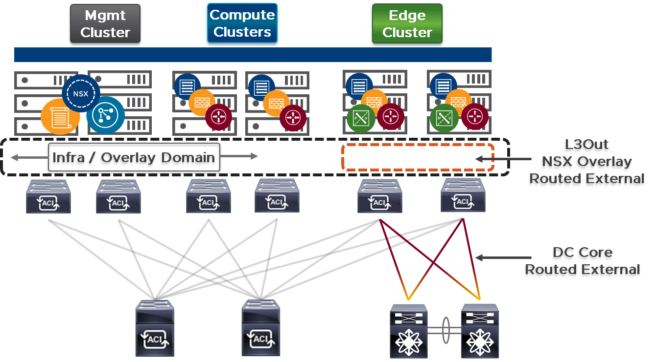
Figure 48: NSX Edges and the L3 Outside Connectivity in Relation to the ACI Domains
The Edge Cluster Connectivity section previously discussed the importance of the NSX Edge cluster use and this connectivity, essentially abstracting the NSX platform from the underlay to allow complete software independence of the application platform. This is key for a complete virtual cloud experience.
The NSX Edge cluster connectivity will require a small complement of objects defining the configuration for routed connectivity. The ACI Layer 3 External Outside Network will contain the following configuration for this document:
- L3 Outside (L3extOut object) – Contains the layer 3 routing protocol selections, the VRF, the associated External Routing Domain, and the switch nodes used for the interface specific configurations.
- Logical Node Profile (L3extLNodeP object) – Contains the layer 3 interface-specific configurations for the routing protocol, for example, BGP Peer connectivity configuration.
- External Networks Instance Profile (L3extinstP or L3Out EPG) – Configures the layer 3 networks exposed to the tenant.
- Default Route Leak Policy (L3extDefaultRouteLeakP object) – This policy stipulates if a default route will be sent and if only the default route is sent.
Creating the L3 Outside object requires consideration of which routing protocol will be used when routing between the ACI border leaves and the NSX overlay. The following provides some guidance in choices:
- BGP – If using BGP, eBGP would be the most likely option since the NSX overlay can be managed as a separate routing domain within the fabric, providing easier manipulation of the routes permitted into and out of the networks from the NSX overlay. Also, there are no requirements to establish iBGP relationships between the NSX edges or edge nodes when eBGP is used for the NSX Edge routing into the external network. eBGP is preferred over iBGP at this juncture due to inherent issues with iBGP. ECMP support is available for two to eight edge routing instances when using BGP.
- OSPF – If using OSPF, consider which type of area(s) will be configured for the NSX overlay environment. It is most likely advantageous to design the NSX overlay as the stub network. In doing so, NSX for vSphere provides support for NSSA OSPF areas as the use of “redistributed connected” for the configured networks of the NSX edges or tenant edges, and distributed router necessitates support for NSSA. The use of OSPF between the NSX edges (NSX Data Center for vSphere only) is supported along with ECMP, up to 8 edge appliances.
- Static Routing – NSX Data Center for vSphere supports static routing without use of ECMP routing with NSX edges. For this reason, it is advisable to use one of the previously discussed dynamic routing protocols when routing between the NSX overlay and the external networks. NSX Data Center for vSphere also calls for the use of a floating static route configured with a higher administrative distance in case of a control plane failure within the tiered routing of the NSX overlay. NSX-T for Data Center supports ECMP with static routing in conjunction with BFD to detect the loss of an uplink or connection to its adjacent router.
With ECMP support available through a variety of means, it is advisable to use a dynamic routing protocol whenever possible to maximize north-south routing capacity and availability between the NSX overlay and the external network. This document uses an eBGP configuration for the routing protocol and the layer 3 connectivity between the NSX edges and the ACI border leaves.
Using the small set of objects defined in this document, the NSX Edge connectivity essentially wipes away much of the operational portion of continuous administrative overhead in configuring ACI external connectivity on an ongoing basis. The only requirement may be to scale out the edge connectivity as the NSX platform workloads increase. This will be relatively minimal and a welcomed operational aspect when scale needs arise.
3.4 Configuring ACI Border Leaves Connectivity
There are a series of prerequisite objects that must be created, starting with the Route Reflector Policy and then moving back to the NSX Tenant container object within ACI, to complete the layer 3 external routing configuration.
3.4.1 Configuring the ACI Spine Route-Reflector Policy
For ACI to use learned external routes, there is a prerequisite System Route-Reflector Policy, which is configured for global usage. ACI leaf and spine architecture use MP-BGP as a control plane distribution service of external routes to the internal fabric and tenants. Under the BGP Route Reflector Policy of the System Settings tab, add two spine Node IDs to the Route Reflector Nodes along with an assigned Autonomous System ID for the fabric. Figure 49 displays the configuration of the External Route-Reflector Nodes.

Figure 49: ACI Spine MP-BGP Route-Reflector Policy
This policy will permit the distribution of routes learned from the NSX Overlay and the ACI Fabric as well as the ACI Fabric’s routing connectivity with the data center core and vice versa if necessary. NSX Data Center designs do not normally require leveraging these routes for distribution as a default route is all that is required for the NSX overlay.
3.4.2 Configuring the Layer 3 External Routing Object
Create the L3 Outside object under the External Routed Networks node of the NSXonACI tenant. Ensure that the VRF assigned is the VRF created for the tenant. Assign the External Routed Domain to be used for the NSX overlay connectivity. Figure 48 displays how the External Routed Domain will be used to map the NSX Edge connectivity to the ACI fabric. This domain was originally created under layer 3 external domains of the Fabric Access Policies. Select the protocols that will be used with this external routing. In the case of this document, BGP should be selected.
3.4.3 Configure the Logical Node, Logical Interface Profile Objects, and the BGP Peer Connectivity Profiles
The Logical Node Profile lists the switch nodes used for the external routing and will later contain the BGP Peer Connectivity Profiles defining the BGP Peer addresses and interfaces used for the control plane communication. There should be at least two Node IDs selected denoting the two ACI border leaves for highly available external connectivity. A router ID is required to be configured along with an optional loopback value for each ACI node assigned for external routing use. The BGP Peer Connectivity Profiles are best created after configuring the following Logical Interface Profile objects. This document stipulates a need to create a single Logical Node Profile containing the two border leaves. Individual topology variances may require a different configuration assortment.
The Logical Interface Profile Objects list the interfaces configured per each ACI border leaf listed in the Logical Node Profile for external routing. A minimum of two border leaves will be used, resulting in creating a minimum of two Logical Interface Profiles, one for each border leaf.
There is one specific set of values this profile will initially contain, the switched virtual interfaces (SVIs), to be used for the routing interfaces. SVIs are best used in this configuration due to the nature of the physical switch interface use. In most cases, the switches’ physical interfaces downlink to the hypervisors hosting the NSX edges, will provide switching and the pathway for routing. Thus, it is necessary to use SVIs and not routed interfaces or routed subinterfaces, the other two choices available for use with ACI layer 3 routing. Again, the BGP Peer Connectivity Profiles may be created here but will be created in a later step in this guide.
In creating the SVIs, it is required to configure the static VLAN encapsulation used for the connectivity provided by the physical interface for the logical connectivity. Ensure a unique VLAN is chosen from the VLAN pool associated with the external routing domain configured during the earlier making of the fabric policies. Figure 50 displays the creation of the SVIs to be used for layer 3 external domain routing off one of the Logical Interface Profiles of one border leaf.

Figure 50: Multi-Step Wizard Creating the Interface Profile and the SVIs for the Layer 3 Connectivity
The wizard interface within the ACI APIC has three steps, with Steps 1 and 3 pictured. Step 2 provides configuration of protocol-specific items for use of BFD and HSRP; the defaults were accepted here.
Note: Neither of these protocols is used with NSX Data Center for vSphere Edge Cluster design. The NSX-T Data Center design can use the BFD protocol, especially with ECMP configured routing using static routes for the external route connectivity of the edge nodes.
Since each SVI will be required to use each physical connection pathway required to provide logical peering with NSX edges from each hypervisor, each SVI will require a logical interface per every physical interface. Figure 51 displays the logical pathway that is required to be defined by an SVI Interface Profile. If there are two ESXi hosts for the NSX Edge Cluster with two physical interfaces used by each host, there will be a need to map an SVI per each host per transit VLAN.
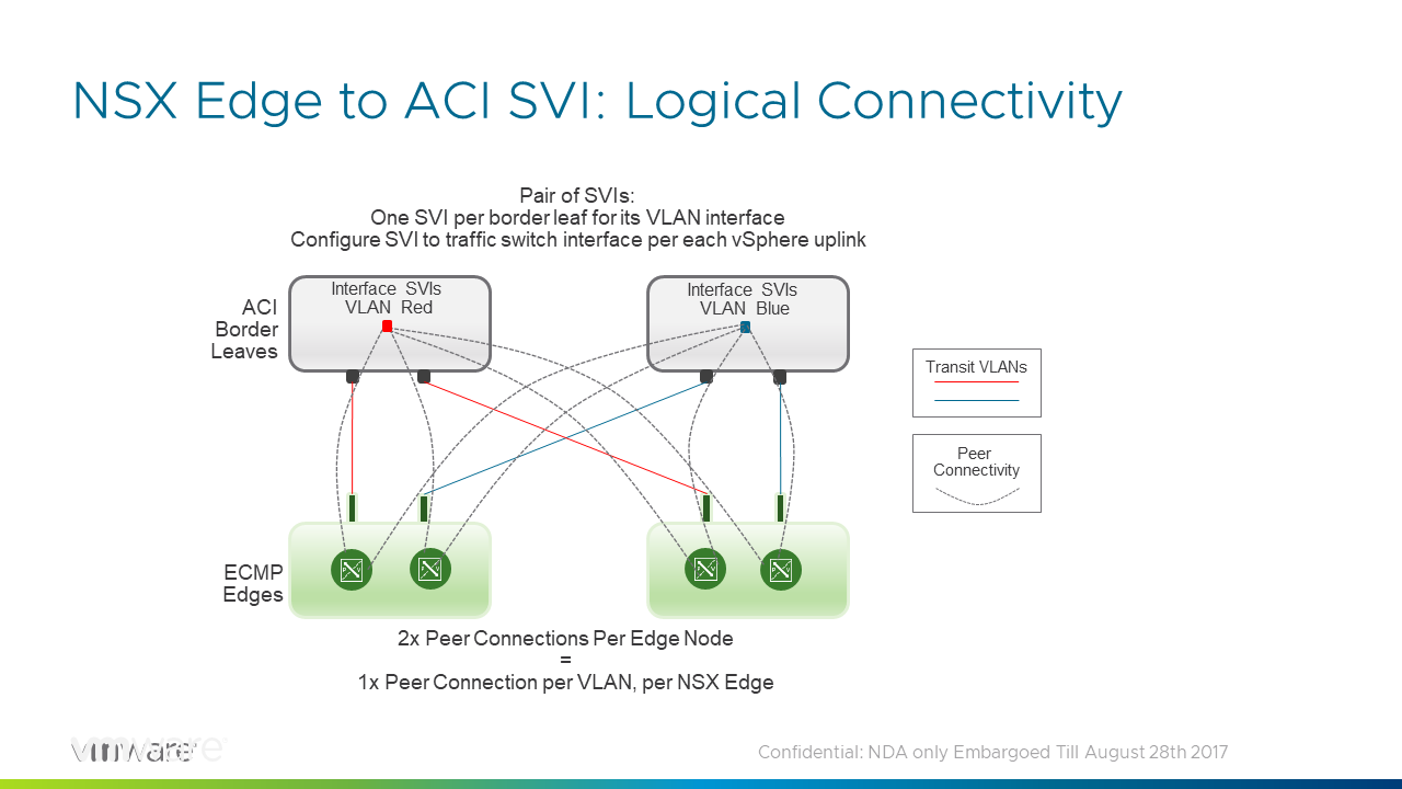
Figure 51: Logical BGP Peer Connectivity for the NSX Edge Cluster
At this point, BGP Peer Connectivity Profiles can be created using the ACI SVI interfaces as the source of the peer adjacency connection to the NSX edges. Each SVI will use those same predefined pathways for the transit VLANs to accomplish adjacency communication. The resulting number of BGP Peer Connectivity Profiles will be equivalent to two times the number of edge nodes used for the ECMP connectivity of the NSX Edge cluster. Figure 51 also displays the logical connectivity of the BGP peers and the two transit VLANs using four NSX Edge nodes on two separate hosts.
The BGP Peer Connectivity Profile requires the following to be defined:
- Peer IP address
- Remote Autonomous System number
All other values of each Peer Connectivity Profile are optional and dependent upon the needs of the environment concerning the routing protocol features desired for use. The NSX Edge nodes are used for the NSX Edge for vSphere Edge Cluster, very little else is required. The peer connectivity can borrow the use of the assigned BGP AS for the fabric as is commonly done in environments not requiring extensive use of multiple autonomous systems. If this is the desired topology, do NOT assign the use of the internal fabric AS to the Local-AS Number attribute of any of the configured BGP Peer Connectivity Profiles.
Figure 52 displays the resulting set of BGP Peer Connectivity Profiles created for a topology with two ACI border leaves with two ESXi hosts. Each ESXi host contains two edge nodes, and each edge node will use both transit VLAN uplinks from their respective hosts for their two defined peer connections. This would mean there should be two BGP Peer Connectivity Profiles per SVI. Since there are two defined SVI interfaces per Logical Interface Profile, this results in four BGP Peer Connectivity Profiles per each of the Logical Interface Profiles.

Figure 52: ACI Logical Interface Profiles
To ensure the proper timers are set for these connectivity profiles, ACI now provides an ability to set a single BGP Protocol Policy per each defined Logical Node Profile. In this design, a single Logical Node Profile is used and therefore a single BGP Protocol Policy should be set with a BGP Timers Policy. The routing protocol timers are based on standard design ideals when using ECMP with NSX edges. The Keepalive interval is set to 1 second with the Hold interval set to 3 seconds.
Each of the external routed networks can also leverage a Default Route Leak Policy. This provides a means of injecting a default route sourced from the ACI leaves into the NSX edges. This single object alleviates any necessity to configure an additional policy that sends external routes to the NSX overlay.
3.4.4 Configuring the Networks Object (L3extinstP) or L3Out EPGs
The Networks object provides accessibility for the tenant to outside networks. The outside networks are exposed to the tenant EPGs through a contract. The Networks object required for this document does not demand many settings as per the goals of this design. Subnets are required to define the NSX overlay for the ACI tenant’s access. There are several types of subnet Scope values to define the L3Out’s connectivity. The only required Scope value to define subnets is the Scope named External Subnets for the External EPG. This defines the subnets the ACI tenant may access with allowed contracts. Summarizing the subnets with as few subnet objects as possible is best. Figure 53 displays a configured L3Out Networks object providing access to a summarized IP domain space in the NSX overlay.

Figure 53: L3Out EPG for the L3 External Network Access to the NSX Overlay
Note: The Cisco best practice ideal when defining the External Subnets for the External EPG is to not use the default route value (0.0.0.0/0) on more than one L3Out of the same VRF. It is quite likely that the northern L3Out (connectivity of the ACI fabric to the data center core) will require the use of the 0.0.0.0/0 route value to define all accessible routes and may use the same VRF for its routing context. Remember, the data center switch fabric in the standard NSX design will usually serve as a transit network for connectivity from the data center core (and quite likely the Internet) to the NSX overlay networks.
The other ACI scope values are not required to have any defined subnets for access to the NSX overlay. All ACI tenant networks define access using settings within the defined subnets of either the bridge domain networks or within the subnet node of the EPG. Export and import are only necessary to permit specific transit network access, which the NSX overlay does not require by default.
For the ACI fabric configuration, all that is left is to define ACI contracts for ACI tenants to permit communication to the L3Out. Another way to permit traffic is to use the vzAny object to permit all communication to the ACI tenant since NSX will provide micro-segmentation.
3.5 Summary of the ACI Underlay
The construction of the ACI underlay broken into two parts allows for modular design variability in terms of the following:
- Scaling the switch fabric using minor adjustments to one or more of the constructed Fabric Access Policies
- Choice of fabric connectivity using either independent Active/Active connectivity versus Cisco ACI vPC
- Additional building of network-centric security groupings for inclusion of other virtual or physical VLAN-based workloads
The design of the ACI underlay chosen for this document is based upon the ACI network-centric model for the fabric. The fabric is configured for optimum operational use and scale. The underlay is meant to provide robust infrastructure support disaggregated from the private cloud environment that supports the NSX Data Center overlay. The overlay design is chosen as the basis for application workload deployment, as more and more customers are looking for cloud agility within the data center. Abstracting the underlay from the deployed workloads removes dependency upon the underlay for service provisioning, the inherent security of NSX Data Center, and the agility to seamlessly manage and move workloads between sites and public clouds.
4 NSX Deployment Considerations
This design assumes that a standardized deployment model of NSX will follow the creation of the previous set of ACI abstractions and constructs. For instance, VMware vCenter Server and vSphere infrastructure hosts, if not already deployed, will be installed followed by NSX Data Center. Cisco ACI has a variety of other deployment options and these were considered in formulating the network-centric architecture in this document. The design choices outlined in this document for Cisco ACI infrastructure normalized the propensity of ACI for complexity in its application approach. This design for the switch underlay enables the customer to deploy a fast and efficiently managed switch fabric. Scaling the underlay requires only a modest number of additions or edits to the configuration with no disruption in serviceability of the deployed application services. The NSX platform abstracts the underlay modifications for the most part, providing a deployment environment that is free from disruptions caused by updates, changes, and HA planned and unplanned failures.
However, there are a few design ideals that should be discussed in more detail, considering the value of inherent features, design choices that are recommended, and a few plausible design variations, with respect to the recommendation offered previously specific to use of an ACI fabric. Here is a list of the items included in this discussion:
- Use of a single IP prefix for each of the kernel services required of the NSX infrastructure networks (Mgmt, IPStorage, vMotion, and Overlay)
- NSX control plane choice for Unicast (NSX Data Center for vSphere) or Head-end (NSX-T Data Center) in most situations
- NSX layer 2 bridging requirements of the ACI underlay
- Leveraging driver offloads for line-rate performance in software
- Single ACI Application Profile, VRF, and Tenant
4.1 Choosing the IP Prefix Size of the NSX Infrastructure Networks
Cisco ACI fabric or any VXLAN-based underlay appear as a large layer 2 switch from an endpoint perspective. Even though each ToR in the fabric can serve as the distributed gateway for all subnets instilled within the rack of hosts served by the ToR, the physical underlay’s VXLAN fabric also has the ability to provide L2 adjacency to endpoints of any network device of the physical underlay. This can be leveraged by the NSX infrastructure design to avoid messy multiple subnet designs for infrastructure communication. This further reduces the requirements for the number of ACI tenant abstractions, and more specifically EPGs representing the groupings of the NSX infrastructure endpoints.
This design ideal factors the largest prefix available to the network designer for these networks into the choice. This design recommends nothing smaller than a /22 prefix size. This provides a capacity of 512 hosts, using a minimum of two IP addresses of the pool from the IP prefix chosen. This allows the underlay to play its role in providing a highly simplified transport network. There are no routing needs between endpoints in the infrastructure groupings. This will add the burden of replication to the source hypervisor. The control plane discussion following this section delves into capacity availability as another leveraged ideal.
Remember, this document’s primary goal is to provide a pathway for simplified application deployment with an NSX overlay, while avoiding the complex entanglement using the infrastructure to directly service application dependencies. A previous discussion on NSX Edge cluster design complements this ideal.
4.2 Choosing the NSX Control Plane
In deciding between the selection of control plane settings for a transport zone or a specific logical switch, several items normally present themselves as decision points:
- What is the infrastructure topology in relation to layer 2 pods or leaf/spine with layer 3 demarc at the ToR?
- Will there be a horizontal or vertical cluster deployment of the transport nodes (compute hypervisors) in an NSX Data Center for vSphere topology (more specifically, is (are) the VDS(s) deployed across multiple racks aligned with the vSphere clusters)?
- What is the number of IP hops built into the transport zones connectivity (that is, are there routed hops between the tunneling endpoints)?
- What is the scale of the use of individual logical switches in the deployment of application services on the NSX platform?
- What are the BUM feature requirements or dependencies called out by the applications deployed in the virtualized network? Are there L2 Multicast application needs?
There are many other valid questions to consider, but these tend to be the main design concerns for choosing the NSX Data Center control plane service option. These decision points should not be disregarded, but we can summarize a few useful ideals to help in this decision.
One of those useful ideals to justify the control plane decision is the large I/O capacity available within the Nexus switch leaf/spine architecture. It should be noted this capacity is available whether the Nexus switches are running NX-OS standalone or ACI mode, or running any other switch vendor’s fabric. These modern switch fabric links use between 40 to 100 Gb/s fabric connections with each uplink from the leaves to the spines. This large I/O capacity should be considered and compared to any recently captured capacity flow values if available. If the legacy switch infrastructure is using a substantially reduced fabric link capacity prior to the switch fabric upgrade, this would lend credence to an abundant availability after an upgrade. If the comparison yields the likely results one would expect, then the fabric should not be the limiting factor in deciding the control plane setting for the NSX logical overlay.
The more relevant ideal would be the overhead placed upon the hosts supporting the network virtualization traffic. This overhead would be defined in terms of compute, network, and memory when it relates to replicating BUM traffic.
Starting with broadcast traffic needs, the concern for supporting broadcast traffic within the overlay would be minimal. NSX control planes’ proactive unknown Unicast support and ARP suppression service for switched and routed traffic minimize a substantial portion of the BUM traffic that is normally generated. BUM traffic can also be limited by L2 NSX DFW rules by allowing only ARP and DHCP, and possibly blocking any unnecessary BUM traffic.
This leaves multicast as the only wild card, more specifically L2 multicast support in terms of service load placed upon the source hosts for replicating the traffic. With modern hosts having a larger compute capacity due to the ever-increasing core capacity in today’s physical processors, there is less concern that compute capacity will be exceeded prior to network or memory needs. NSX control plane appliance maximum capacity usage is 4 vCPUs per appliance. Since each host is in a Management cluster, memory capacity for the most part is unconstrained by the NSX control plane’s choice, as this represents only a fraction of the memory consumed on a host.
4.3 NSX Layer 2 Bridging and Required ACI Underlay Configuration
To facilitate the use of layer 2 bridging of NSX overlay to VLANs, an ACI EPG that is VLAN-backed is required to provide the connectivity into the ACI infrastructure from the NSX host providing the bridging. The ACI EPG will be constructed within the NSX ACI tenant portion of the configuration and will require an additional ACI EPG per each bridged VLAN from NSX. The ACI leaf interfaces will require a static EPG and VLAN mapping where the NSX hosts are providing the active and standby layer 2 bridging connectivity. Each additional ACI EPG constructed for NSX bridging will also use its own configured ACI bridge domain.

Figure 54: Configuring NSX Overlay to VLAN Bridge
Use of a configured subnet and distributed gateway for each ACI bridge domain should take into consideration whether the default gateway for the bridged overlay to VLAN segment will use distributed routing of NSX or an ACI distributed SVI. Configure all networks to use the single VRF constructed for the NSX over ACI tenant.
4.4 Software Performance Leveraging Driver Offloads and Inherent Security Through NSX Distributed Firewall
The NSX Data Center software-defined networking platform leverages numerous offload capabilities in the hypervisor, the physical NIC, and the virtual NIC of virtual workloads. This provides performance that either meets or exceeds performance and scale of security within the hardware switched underlay inclusive of ACI. NSX Data Center has already publicly displayed performance upwards of 100 G of throughput per node for typical data center workloads. The following VMworld sessions focused on NSX performance:
These presentations demonstrated the use of standard TCP optimizations such as TSO, LRO, and RSS or Rx/Tx filters. These commonly used offloads drive incredible throughput and were demonstrated in the live demos of the previously cited VMworld sessions. These optimizations consumed a small fraction of CPU to provide their benefits. They originally existed in non-overlay topologies. NSX Data Center has been leveraging the same set of TCP optimizations for VXLAN and Geneve overlay-backed topologies.
Further, micro-segmentation with NSX Data Center is inherent in the hypervisor and provides its service at line-rate. NSX Data Center micro-segmentation does not require the following to perform its service:
- Steering packet flows to remote physical firewalls consuming enormous amounts of I/O capacity for this east-to-west traffic.
- Likewise, directing packet flows to remote virtual firewall appliances that not only consume the same amount of east-west I/O capacity as the previous physical firewall use will, but performance degradation of a user space virtual appliance.
- Implementation of an in-host firewall agent to program the use of the Windows Advanced Security Firewall or IP Tables of a Linux virtual workload. These two solutions provide zero isolation of the solution as it is ingrained in the guest VM and has proven over time to be unreliable.
- Complex service graphs or policy-based routing (PBR) schemes to direct workflow between the app tiers.
4.5 Use of Single ACI Tenant, Application Profile, and VRF
This document recommends a single ACI tenant for the container of the Application Network Profile. There is little value gained by adding ACI constructs for managing the vSphere and NSX Data Center infrastructure and overlay communication by separate traffic types, functional NSX Data Center clusters (Management, Compute, and Edge), or finally by the vSphere cluster for the compute workloads. Operationally, the least complex deployment of the infrastructure, including ACI, the hypervisors, and NSX Data Center, accelerates the ability to move into deployment.
Cisco ACI does provide several operational tools specific to an ACI underlay. SPAN, port tracking, and several other monitoring tools can provide their respective value determining infrastructure connectivity and packet captures for analysis without the need for additional ACI Application Network Profiles (AP) constructs. There are specific ACI policy constructs for their respective operational needs.
There are some ACI-specific tools such as “Atomic counters” that provide some visualization of the communication flow in the fabric. The prevailing wisdom is to create separate AP constructs for specific functional clusters to view I/O consumption by the cluster. Separating the NSX clusters into various AP may seem like a logical path to visualize I/O consumption more granularly. Using compute cluster boundaries with a complex weave of ACI constructs, to determine where I/O capacity consumption is greatest, misses the point of the compute infrastructure’s purpose in a private cloud.
The infrastructure hosts are meant to be treated as one large pool of compute capacity, storage for HCI, virtual networking, and inherent security servicing. In the SDDC, consumption of these resources is spread across the entirety of the clusters. It is quite likely that application workflows will stretch across hypervisor cluster boundaries and blur that line to such a degree that it makes the cluster boundary a meaningless partition for flow and I/O capacity analysis. Therefore, Cisco tools are more attuned to gathering flow statistics for detecting drops and miscommunication between the infrastructure endpoints within the underlay. The endpoints in this case are the host infrastructure network endpoints. For the application endpoints, NSX Data Center will provide the ability to detect application connectivity down to the individual workload, using the Flow and Packet Trace tools of the NSX Data Center toolset.
Providing rich flow analytics is done with tools built for network virtualization such as vRealize Network Insight. Even Cisco has determined that its inherent flow analysis tools offer little insight in this same area, and suggests the purchase of their own flow analytical tools. The true value is to understand where capacity is consumed on a per-application basis and even down to a per-flow basis.

Figure 55: vRealize Network Insight: One of Many Customizable Flow Analysis Dashboards
As previously mentioned, network virtualization requires operational tools built to understand the communication path from an endpoint in the virtual overlay through the physical network and to the destination endpoint. Tracing that path through logical switches, distributed firewalls, and logical and physical routers provides the full context of workflow communication. vRealize Network Insight can quickly provide this visualization path. Further, default dashboards may help you discern the “Top Talkers” based on a variety of metrics. Custom dashboards may be constructed to target application workloads by flow, traffic volume, session counts, and flow counts. Application-centric administration should operate at the application workload layer, and not concern itself with the infrastructure except as a means of reliable transport.
5 Conclusion
NSX is agnostic to the underlay. The full stack of virtualized network services that come with NSX can be leveraged using any physical underlay, including Cisco ACI. NSX can be deployed in a complementary fashion with Cisco ACI when ACI is used as a physical underlay.
NSX brings significant benefits to customers, which a fabric-only solution such as Cisco ACI cannot provide. These include secure micro-segmentation, end-to-end automation of networking and security services, and enabling application continuity. Cisco ACI provides a limited set of functionalities out of the box for network and security virtualization. While NX-OS mode is the recommended option for Cisco Nexus environments because of the flexibility of topology and features supported by a variety of Nexus lines of switches (Nexus 3xxx, 56xx, 6xxx, 7xxx, and 9xxx), customers who choose ACI would still be able to leverage the full benefits of NSX.
Recommendations provided in this document must be followed in order to ensure success for any combined deployment. Any deviation from the recommendations introduces a risk, since the ACI fabric is a non-standard networking solution.