
Multi-TEP High Availability
Introduction
A tunnel end point (TEP) is a virtual interface that can serve as an uplink for overlay traffic. On an ESXi host, a TEP is tightly associated to the physical interface through which it sends and receives its traffic. In the current TEP high availability (TEP HA) model, a TEP never fails. If the link of the ESXi interface to which a TEP is associated goes down, the TEP is simply moved to another ESXi interface picked from the default teaming policy. This redundancy model is consistent with the way vSphere deals with its VLAN uplinks. There are, however, a few failure scenarios that the approach does not address.
To handle these, NSX 4.1 introduces a new feature, called multi-TEP high availability (multi-TEP HA), that add the two following enhancements to ESXi transport nodes with multiple TEPs:
- Detect when a TEP cannot acquire an IP address via DHCP.
- Detect when a TEP cannot reach any of its peers through its associated physical interface (assuming that the physical interface itself is still up.)
In those cases, the TEP itself will be considered failed, and its duty will be handed over to another TEP -- hence the requirement that multiple TEPs exist on the transport node. (Note that this feature only applies to ESXi transport nodes, not edge transport nodes.
This document explains how this feature works. It begins with a concise summary of the current TEP-HA mechanism, then details how multi-TEP HA builds on the top of it to handle additional failure scenarios.
Tunnel End Point High Availability
TEPs are associated with a physical uplink and transport nodes can have one or several TEPs, depending on their default teaming policy. With a failover order teaming policy, traffic only flows through a single active uplink. As a result, the transport node only needs a single TEP. With source teaming policies (a source MAC address or source port ID), traffic will be distributed across multiple active uplinks listed in the teaming policy, and one TEP needs to be instantiated for each of those physical uplinks.
TEP high availability works the same, whether there is one or multiple TEPs. When the link of the interface associated to a TEP goes down, the TEP migrates to another interface in the teaming policy with a link up. The following diagram illustrates this model. Here, ESXi1 is using a source teaming policy (vmnic0 and vmnic1 active), resulting in the creation of a TEP for each of its physical uplinks (vmnic0 and vmnic1). ESXi2 is configured with a failover order teaming policy (vmnic0 active, vmnic1 standby), and only the first physical uplink listed in this policy (initially vmnic0) is associated to a TEP.
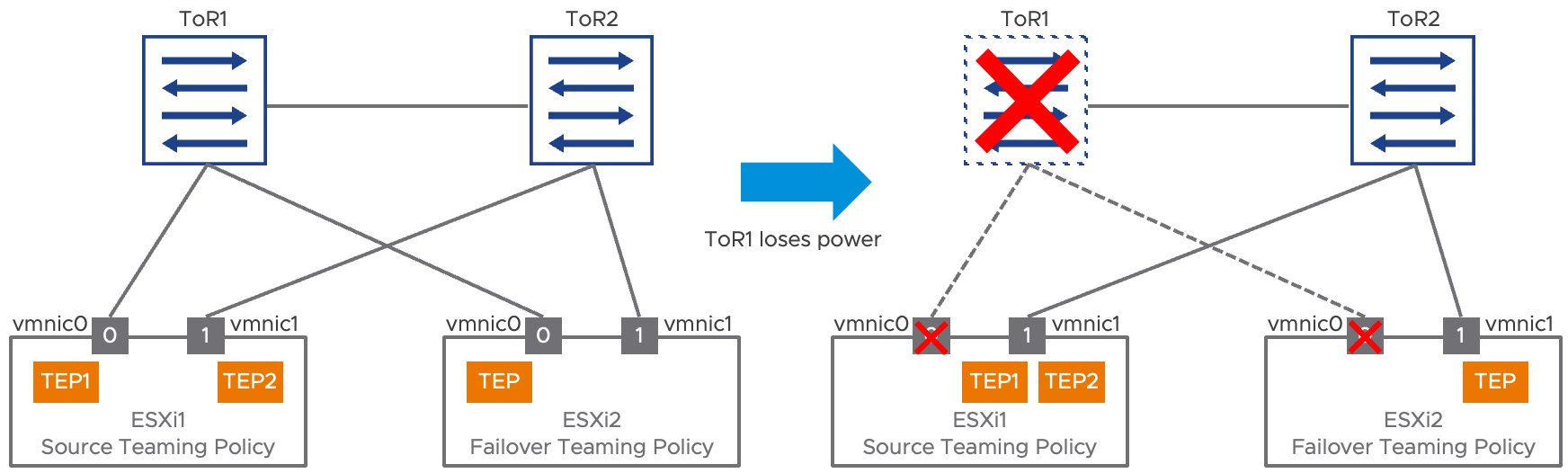
Figure 1: TEP high availability
When the top of rack switch ToR1 fails, vmnic0’s link goes down on both ESXi1 and ESXi2. For both ESXi hosts, the impacted TEP is migrated to vmnic1, the remaining operational uplink within the teaming policy. Note that the TEP itself is never considered to have failed but depending on the status of its “preferred” interface, it might move to a secondary interface. This implies that all the uplinks part of a teaming policy are expected to be layer 2 adjacent
The following diagrams goes a little bit further into the architecture of an ESXi host featuring multiple TEPs. In this example, the virtual machines (VM1, VM2, VM3 and VM4) are attached to an overlay segment. The virtual machines can communicate directly with each other within the host using this segment. The source teaming policy also associates those four VMs to the different TEPs: here VM1 and VM2 are associated to TEP1, while VM3 aVM4 are associated to TEP2. What this VM to TEP association means is that traffic going from, say, VM1 will be forwarded out of the ESXi transport node on the overlay, using TEP1 as a source. Overlay traffic from remote hosts toward VM1 will also be received by TEP1. This association is reflected in the MAC address table for the segment, represented in the right side of the diagram. This table is synchronized to all remote transport nodes.
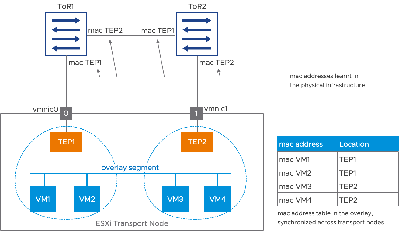
Figure 2: VM to TEP association
The diagram in Figure 2 also shows how the MAC address of the TEPs are learned in the physical infrastructure. For example, top of rack switch ToR1 has learned that TEP1’s MAC address is on the downlink toward vmnic0 and TEP2’s MAC address is reachable via the inter switch link.
Now, let’s suppose the link between ToR2 and vmnic1 goes down. The PHY of vmnic1 declares the link has failed, and TEP2 is immediately moved to vmnic0. To update the MAC address tables in the physical infrastructure, a RARP is sent on vmnic0, using TEP2’s MAC address as a source. This convergence is represented in Figure 3 below:
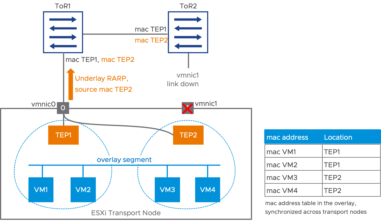
Figure 3: TEP HA behavior in case of an uplink failure
Following the flooding of the RARP packet, the MAC address tables in the physical infrastructure direct traffic for TEP2 directly toward the downlink of ToR1. This mechanism is extremely efficient. As soon as the link of vmnic1 is declared down, the transmission of a single packet on vmnic0 potentially recovers connectivity for all the VMs impacted by vmnic1’s failure. Figure 3 represents the updated MAC addresses in the physical infrastructure in orange. Notice that the MAC address table of the segment, in the overlay, remains completely unaffected by the reconvergence.
Multi-TEP High Availability
The uplink failure recovery implemented for transport node uplinks provided by TEP HA is as efficient as can be, assuming that a link failure is detected by the hardware. Multi-TEP high availability is an optional feature built on top of TEP HA that covers some additional failure scenarios on ESXi hosts with multiple TEPs. More specifically, multi-TEP HA will consider a TEP failed if:
- It cannot acquire an IP address via DHCP.
- The physical interface associated to the TEP cannot send or receive traffic while its link remains up.
The failed TEP will be replaced by a healthy one. This part details the failure detection, the recovery mechanism involved and the way multi-TEP HA behaves when the initial failure condition has cleared.
Failure detection: TEP fails to acquire an IP address via DHCP
TEPs IP addresses are used to establish overlay tunnels between transport nodes. As a result, a TEP cannot function properly without an appropriate IP address. With NSX, TEPs can be assigned an IP address in three different ways:
- Via explicit configuration, when setting up the transport node.
- Picking one available entry in an IP pool, specified when setting up the transport node.
- Dynamically, via the Dynamic Host Configuration Protocol (DHCP.)
With the latter option, it’s possible that a TEP initially gets a valid IP address and operates successfully for an arbitrary period before failing when trying to renew its IP address via DHCP. With multi-TEP HA, this very specific scenario will now lead to the failure of the TEP.
Failure detection: physical uplink up but not able to transmit/receive traffic
The TEPs of NSX transport nodes are running BFD (bidirectional forwarding detection) sessions between each other. Those sessions are used to evaluate the health of the TEPs for the various NSX dashboards. Those BFD sessions can also give an indication of the health of the physical interface associated to the TEP. Once a TEP has established a BFD session with a peer, it indirectly receives the indication that the interface to which it is associated has bidirectional connectivity. When all previously established BFD sessions go down, the TEP can also safely infer that its associated interface has failed, even if its physical link remains up.
The figure below represents the scenario where the link between ToR2 and vmnic1 stops forwarding traffic while remaining physically up. TEPs are running BFD sessions between them at a 1 packet per second fixed rate, which is not configurable by the user. About 3 seconds following the failure, all BFD sessions to TEP2 are down.
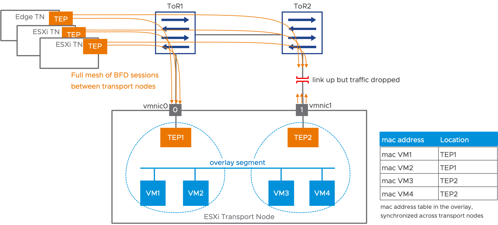
Figure 4: multi-TEP HA, failure detection
After all BFD sessions are down, multi-TEP HA adds another configurable delay before declaring the TEP to have failed.
Reconvergence
Let’s continue using the example in Figure 4 above, where TEP2 has been declared to have failed. The virtual machines that had vNICs associated to this TEP2 need to move to TEP1, the only remaining TEP available. Here, VM3 and VM4 are now going to switch to TEP1 to communicate with the outside world.

Figure 5: multi-TEP HA reconvergence
After moving the VMs to TEP1, there is no MAC address change in the physical network: TEP1 and TEP2 are still associated to vmnic0 and vmnic1, respectively. However, some VMs that used to be reachable via TEP2 are now behind TEP1 and the overlay mac address tables of all the remote transport nodes need an update. This is achieved in two ways: one for a fast update, the other for a reliable update:
- Using the data path, multiple RARPs packets with the source MAC address matching the VMs vNIC’s MAC addresses are flooded on the overlay segment.
- The updated MAC address table is also advertised to the central control plane component, which in turn propagates the changes to the remote transport nodes.
This MAC address table update is an expensive operation compared to the TEP HA equivalent that only required moving a single MAC address in the physical infrastructure. Furthermore, the failure of a top of rack switch, as depicted Figure 1 for example, could result in many hosts simultaneously switching TEP for some of their VMs. But keep in mind that multi-TEP HA is a secondary failure detection mechanism that addresses some corner cases where TEP HA would not converge at all.
Failure recovery
Failing TEP2 instead of moving it to vmnic0 is an important design choice for the multi-TEP HA feature. Because TEP2 remains associated to vmnic1, it can be used to re-establish BFD sessions to remote peers and validate vmnic1’s availability. However, for TEP2 even to attempt to establish BFD sessions with the remote transport nodes, our current implementation requires some vNICs to be associated to TEP2. The recovery mechanism will thus require moving the VMs that had been evacuated to TEP1 back to TEP2. This is a disruptive operation. Furthermore, if the failure was due to a physical uplink problem, TEP2 might not be able to return to an operational state, and VMs would have to be associated back to TEP1. Multi-TEP HA thus provides different options for attempting to recover a failed TEP:
Automatic recovery: After a configurable timer, an attempt is made to move the evacuated VMs back to their original TEP. If the TEP fails to establish at least a BFD session, VMs are evacuated again. Additional periodic recovery attempts are made, following an exponential back-off algorithm. This model has some implication on the connectivity of the impacted VMs. Its benefits are the capability of falling back to a configuration where all the physical uplinks are used, without user intervention.
Manual recovery: The user, via either the CLI or API, indicates that they want to attempt a recovery of the affected TEP. This is the best approach for administrators who want to minimize traffic disruption, as they can verify the problem in the physical infrastructure is solved before moving the VMs back. The drawback is that the VM traffic distribution across the physical uplinks remains affected until this manual step is initiated.
Multi-TEP HA Summary
Multi-TEP HA is a new feature introduced in NSX 4.1.
- It is an optional feature that needs to be enabled explicitly.
- It only works on ESXi transport nodes with multiple TEPs (not edge transport nodes.)
- It builds on the top of TEP HA and provides coverage for some specific failure scenarios:
- TEP cannot retrieve an IP address via DHCP.
- The physical link associated to the TEP remains up while failing to transmit or receive traffic.
- Multi-TEP HA convergence time is on the order of a few seconds, and it is relatively resource intensive, but it covers cases where TEP HA would not have converged at all.
- Recovery is disruptive. The administrator can choose between a preemptive or non-preemptive mode, where the recovery is manually triggered.
LAB example
This section describes the configuration steps required to set up the multi-TEP HA feature in a minimal lab environment. We are going to prepare two transport nodes for NSX and attach a few virtual machines to an overlay segment. Then, we will disrupt overlay communication on one ESXi uplink so that multi-TEP HA kicks in.

The setup consists of two ESXi transport nodes, b35-esxi1 and b35-esxi2, which are part of a cluster called “Compute1.” The three VMs on b35-esxi1 will be enough to create a distribution of their vNICs across multiple TEPs. The remaining VM on esxi2 will ensure that tunnels are set up between b35-esxi1 and b35-esxi2.
Lab Setup
In order to use the multi-TEP HA feature, we need some ESXi transport nodes with multiple TEPs. This is achieved by configuring a source teaming policy applied to at least two uplinks. The following screenshot represents an uplink profile with such a teaming policy:

This uplink profile is used to create a transport node profile (TNP). Finally, this TNP is applied to the “Compute1” cluster.

Creating a host switch profile for multi-TEP HA
As of NSX 4.1, the multi-TEP HA feature can only be configured by API. The user will create a specific TEP HA profile that they can apply directly to a transport node or a transport node profile. In the latter case, the TEP HA profile will apply to all transport nodes driven by the TNP.
Here is an example of the setup for TEP HA “tephaprofile1” using an API call to the NSX manager “nsxmgr.ft.lab”:
{
 "enabled": true,

 "failover_timeout": 2,

 "auto_recovery": true,

 "auto_recovery_initial_wait": 300,

 "auto_recovery_max_backoff": 3600,

 "resource_type": "PolicyVtepHAHostSwitchProfile"
}
Body of the response:
{
"enabled": true,
"failover_timeout": 2,
"auto_recovery": true,
"auto_recovery_initial_wait": 300,
"auto_recovery_max_backoff": 3600,
"resource_type": "PolicyVtepHAHostSwitchProfile",
"id": "tephaprofile1",
"display_name": "tephaprofile1",
"path": "/infra/host-switch-profiles/tephaprofile1",
"relative_path": "tephaprofile1",
"parent_path": "/infra",
"remote_path": "",
"unique_id": "ac2add1d-18f6-4ff5-be38-39cdf5e3c099",
"realization_id": "ac2add1d-18f6-4ff5-be38-39cdf5e3c099",
"owner_id": "b4ccbfde-480a-4ca8-b744-56a7ef5f7e8c",
"origin_site_id": "b4ccbfde-480a-4ca8-b744-56a7ef5f7e8c",
"marked_for_delete": false,
"overridden": false,
"_create_time": 1682541352770,
"_create_user": "admin",
"_last_modified_time": 1682541352770,
"_last_modified_user": "admin",
"_system_owned": false,
"_protection": "NOT_PROTECTED",
"_revision": 0
}
You can retrieve this information using the corresponding GET command:
GET: https://nsxmgr.ft.lab/policy/api/v1/infra/host-switch-profiles/tephaprofile1
Detail of the parameters:
- enabled: Whether the feature is enabled or not
- failover_timeout: The time to wait when a failure is detected before attempting a failover. It will take around 4 seconds for all BFD sessions to go down. There is always a trade-off between detecting a failure quickly and suffering from false positives. This parameter makes it possible to extend the time before the feature takes action.
- auto_recovery: Whether the feature will attempt to recover a failed TEP automatically. When enabled, multi-TEP HA will preemptively attempt to recover the TEP that failed. When disabled, a recovery attempt must be triggered by an API call.
- auto_recovery_initial_wait: The time to wait before attempting to recover a failed TEP when auto-recovery is enabled. Remember that moving VMs between TEPs is a disruptive operation. Ideally, the amount of time configured here should be enough to ensure high confidence that the problem that brought down the TEP in the first place has disappeared.
- auto_recovery_max_backoff: The feature attempts to recover the TEP after auto_recovery_initial_wait. If the attempt fails, meaning that the TEP cannot be brought up (no IP address is retrieved via DHCP or no BFD session comes up), the VMs fall back to an alternate TEP again. The multi-TEP HA feature will attempt another recovery after 2xauto_recovery_initial_wait. This exponential backoff carries on until this time reaches auto_recovery_max_backoff. After that, additional attempts will be made every auto_recovery_max_backoff.
- display_name: Display name of the profile (the feature has no UI in its current version)

Applying the host switch profile to a transport node profile
Now that we have set up a host switch profile enabling multi-TEP HA, it can be applied to a transport node profile or directly to a transport node. Let’s start by applying the host switch profile to the transport node profile that we used to prepare the cluster “Compute1.” This way, the feature will be enabled onto b35-esxi1 and b35-esxi2 in one step.
We can easily find the ID of the transport node profile we created by using the search tool in the UI:
Another simple option is to get all transport node profiles with the following API call:
GET: https://nsxmgr.ft.lab/policy/api/v1/infra/host-transport-node-profiles/
With this ID, we can retrieve the TNP configuration using the more specific GET API call:
Body of the response:
|
|
Edit the body of the response to add the TEP HA profile we created earlier. The changes are highlighted with a grey background below:
|
|
Using the above as a body for the following PUT API call, we update the TNP with the multi-TEP HA configuration, which is instantly applied to all transport nodes in the Compute1 cluster.:
Note that if a host is added to the Compute1 cluster, it will automatically inherit the TNP configuration, including the multi-TEP HA host profile we created.
If the TNP is detached from the cluster, the multi-TEP HA host profile remains applied to all the transport nodes. Also, if a transport node within a cluster configured with a TNP is applied individually to a multi-TEP HA configuration that conflicts with the one for the TNP, it will be shown as a “mismatch” in the UI.
Configuring multi-TEP HA on an individual ESXi transport node
The procedure for applying the host switch profile to enable multi-TEP HA on an individual transport node is very similar to the one we followed for a TNP.
- We retrieve the information for the transport node via the API.
- Next, we add the reference to the host switch profile to the body of the transport node configuration.
- Finally, we call the corresponding PUT API to update the transport node.
First, we need the path for the transport node. There is a special menu in the UI that copies this path directly into the clipboard, as shown below.

We are going to enable multi-TEP HA on a host called b35-esxi3, in the “Compute2” cluster. This host was not prepared for NSX with a transport node profile. Its path is the following:
/infra/sites/default/enforcement-points/default/host-transport-nodes/b35-esxi3.ft.lab
Let's construct an API call for retrieving b35-esxi3 configuration from the above path:
GET: https://nsxmgr.ft.lab/policy/api/v1/infra/sites/default/enforcement-points/default/host-transport-nodes/b35-esxi3.ft.lab
|
|
Now, it’s just a matter of editing the body of the response to the GET API call and adding the host switch profile enabling multi-TEP HA. The changes are highlighted with a grey background in the text below:
|
|
Finally, we execute the following PUT API call, using the edited body to apply the changes to b35-esxi3.
Failing a TEP by bringing down all its BFD sessions
Now that we have configured our minimal “Compute1” cluster setup for multi-TEP HA, we are ready to verify the functionality of the feature. This section demonstrates what happens when a TEP loses all its BFD sessions.
The following is CLI output from b35-esxi1. We’re using the “nsxcli” command to get into the NSX CLI and we are showing the MAC address table associated to the segment called “overlay-segment.” We have edited the virtual machine vNIC MAC addresses so that virtual machine b35-tik1 has a MAC address of 0000.0000.000.1, b35-tik2 uses MAC address 0000.0000.0002 and so on.
|
|
From the perspective of b35-esxi1, there is one remote virtual machine, b35-tik4, that we know is on b35-esxi2. We can also see the three local virtual machines: b35-tik1/b35-tik3 are associated to a TEP with IP address 172.16.35.20, and virtual machine b35-tik2 is associated to a TEP with IP address 172.16.35.21.
We are now going to trigger a failure of TEP1 for b35-esxi1 by cutting its overlay communication with its peers. This is achieved in a very simple way: by removing the transport VLAN from the trunk between vmnic0 of b35-esxi1 and its top of rack switch. As this is just a configuration change on the switchport of the top of rack switch, the link remains up and traffic is still flowing for all VLANs except the transport VLAN.
Within a few seconds, we can see that all the virtual machines of b35-esxi1 are now associated with TEP2, the TEP with IP address 172.16.35.21:
|
|
The UI also reports TEP1 as having failed on b35-esxi1:

After reenabling the transport VLAN on the link between vmnic0 and the TOR, TEP1 remains failed, and the virtual machines remain associated with TEP2. This is because no recovery will be attempted before the expiration of the auto_recovery_initial_wait timer, which we have set to 5 minutes. Instead of waiting 5 minutes, we can trigger a manual recovery, as detailed in the next section.
Manual recovery
Even when the feature is configured to preempt automatically, it’s possible explicitly to re-enable a TEP that was moved to failed state. The VMs will be re-associated to the TEP, and if it’s still not capable of establishing at least one BFD session to one of its peers, it will fail again.
We need to retrieve the path for b35-esxi1 transport node, then create the following POST API call:
Body:
|
|
With this call, the distribution of the virtual machines is restored to its initial state:
|
|
The following CLI commands are available on the ESXi host:
|
|
|
Annex: CLI commands
The following CLI commands are available on the ESXi host:
|
|
|