
NSX Advanced Load Balancer vSphere Write Access Deployment Steps
Overview
To streamline deployment, this document begins with Prerequisites and Recommended Settings sections. Understanding those and having prepared inputs speeds up configuration and can address eventual questions. Configuration steps referring to decision or input from Prerequisites will not contain explanation to shorted size of this document.
This guide was written based on NSX Advanced Load Balancer version 22.1.3. In case other product versions are used, screenshot appearance can slightly differ from provided.
Prerequisites and Recommended Settings
The following are prerequisite infrastructure and environment settings that are recommended in preparation for the deployment and configuration of an NSX ALB Controller Cluster in a VMware vSphere environment.
General Recommendations
- VCSA-managed ESXi cluster(s) with adequate resources and SSD based storage.
- The OVA file for the desired NSX ALB version to deploy Controller nodes. This guide was created based on version 22.1.3, but process will be similar in any subsequent version.
- Two strong passwords strings are required for “admin” user and backup encryption. The password must meet minimum security requirements of at least 12 characters, with a combination of alphanumeric and special symbols.
- Tenancy IP route domain architectural design. For more information please review https://avinetworks.com/docs/22.1/tenants-versus-se-group-isolation/
- Estimate the required Controller Node sizing. For more information review https://avinetworks.com/docs/latest/avi-controller-sizing/
- A valid NSX ALB Cloud Services contract or NSX ALB Cloud Services Trial and credentials to access Cloud Services.
Networking Settings
- It is recommended to utilize FQDN during Cloud configuration.
- It is recommended to configure Remote Backups for Controller Cluster configuration using SCP or SFTP remote servers.
- It is required that VDS based portgroups are created for all Data and management port configurations.
vSphere Settings
- It is not recommended to place Controller nodes or Service Engines in Resource Pools.
- Controllers and SEs are put into vSphere Distributed Resource Scheduler (DRS) exclusion group https://avinetworks.com/docs/latest/drs-and-anti-affinity-rules-in-vmware-vsphere-environments/.
- Log processing requires fast disk access, so SSD disks are recommended for both Controllers and SEs. Refer to sizing guidance for information about disk space distribution https://avinetworks.com/docs/latest/avi-controller-sizing/#allocating-disk-capacity.
- Thick disk provisioning. If not existing, create a storage policy with Thick Provision Lazy Zeroed disk format.
- Controller VM memory and CPU are reserved in vSphere VM properties.
- Starting with 22.1.1, NSX ALB supports Content Libraries for SE image storage, which is the recommended way of Cloud configuration.
- It is recommended to have a dedicated user to configure the vSphere cloud. Summary of user permissions are given in Appendix A. The administrator@vsphere.local user should never be used.
Controller Node Deployment
The following are the recommended steps to deploy a Controller node in a vSphere environment. The steps and diagrams reflect that of a vSphere 6.7 environment, however the steps can be used for a vSphere 7.0 environment.
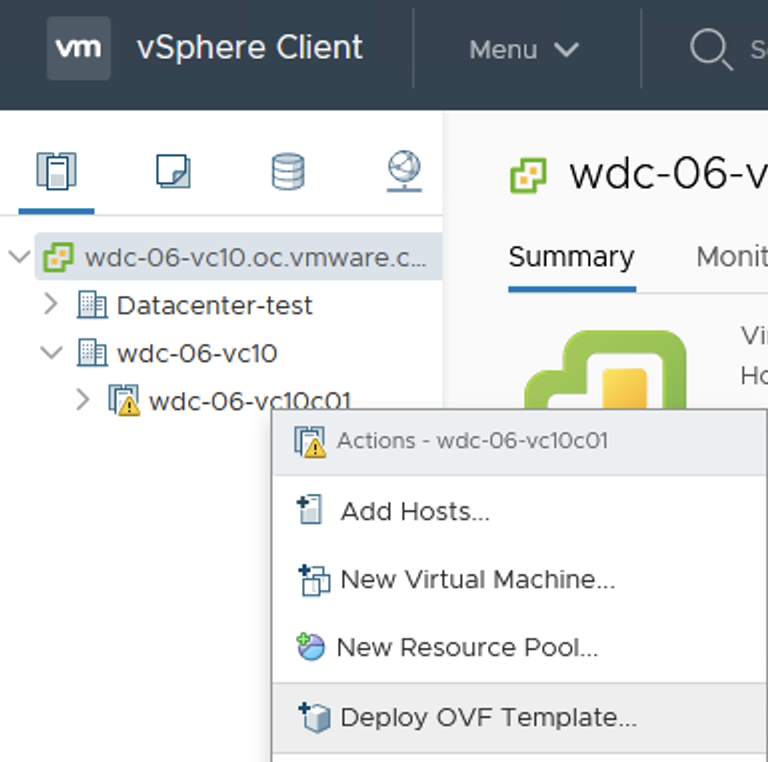
- In the vSphere client, right-click the desired cluster and choose “Deploy OVF Template”:
-

In the Select an OVF Template tab of the pop-up window, select “Local file”. Select the Controller OVA file in the file explorer window.
- Click Next.
- In the Select a name and folder tab of the pop-up window, provide an appropriate name following your company’s naming convention. If you will be deploying a 3-node cluster, please name the nodes accordingly. Finally, select the vSphere Folder that the VM will reside.

- Click Next.
- In the Select a computer resource tab of the pop-up window, choose the compute resource that the VM will reside (Cluster, Host or Application Resource Pool).

- Click Next
- In the Review details tab of the pop-up window, click next.

- In the Select Storage tab of the pop-up window, if possible select SSD-backed datastore, and for non vSAN datastores select the disk format as Thick Provision Lazy Zeroed.

- Click Next.
- In the Select networks tab of the pop-up window, select the Management Portgroup as per the pre-requisite requirements.
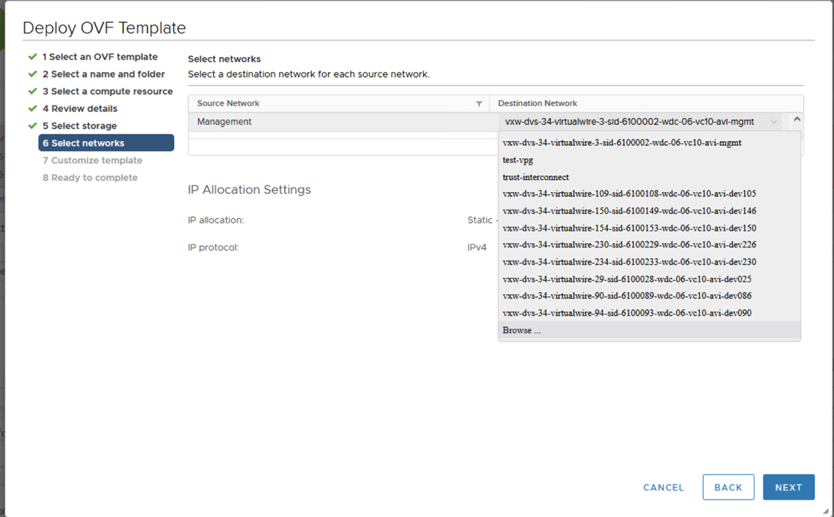

- Click Next.
- In the Customize template tab of the pop-up window, provide the Management IP address, subnet mask and Default Gateway if you ae utilizing static addressing. Other settings can be left blank.

- Click Next.
- In the Ready to complete tab of the pop-up window, review the deployment input. Once ready, Click Finish. Leave the VM powered off, further VM configurations will be outlined in the following section.
- If you are deploying a 3 Node Controller Cluster, repeat the above steps for remaining two Controller Cluster Nodes.
NOTE: Starting with NSX ALB version 22.1.3, IPv6 Management communication is possible between Controller and SE. As of this version, management interface (the one defined during ova deployment) should have IPv4 address. Configuration steps for enabling SE-Controller IPv6 communication are given later in this guide.
Editing Controller VM settings
Once the Controller Nodes have been deployed, we need to configure the VM resources to ensure they are aligned with the recommendations outlined above.
Resize the CPU, RAM and Disk to reflect the recommended sizing scale outlined above. Make sure your settings are consistent between all nodes in cluster. While 128GB is a minimum requirement for Controller VM, VMware recommends at least 512GB to accommodate longer logs storage span.
The diagram below depicts a Medium sized Controller with reserved CPU and memory. The base clock of the hypervisor’s CPU in this case is 2.1GHz, thus full reservation yields 21GHz or 21000MHz. Check your ESXI node’s summary page to choose the correct values in your specific case:


It is recommended to put the Controller Nodes in the DRS exclusion list, as well as create an anti-affinity rule of type “Separate Virtual Machines” to keep Cluster members on different esxi hosts.

NOTE: If your setup requires IPv6 Management: for each of three Controller nodes, edit VM properties, click “Add New Device” and choose “Network Adapter”. Make sure it is connected to the right DVPG and “Connected” as well as “Connect at Power On” checkboxes are selected. It is important to perform this step before forming a Cluster. Specific configuration steps for activating IPv6 Management address are given later in this document.
Power on all three deployed Controllers.
Leader Controller Configuration
The Following steps will need to be performed only on ONE Controller Node, also called the Leader Node.
- In a browser window, navigate to the first Controller Node https://ControllerManagementIP/, you will be redirected to admin setup page.
- Specify a new password for the “admin” user. You can specify an e-mail address for the “admin” user – it will be used in case the password needs to be restored as well as Alert configuration.

- Click Create Account button.
-

On next screen complete the initial configuration. Enter a passphrase that will be used to encrypt the backup files, as well as the DNS resolve and Search Domain.
- Click Next.
- In the next section, select the desired SMTP server used for event processing. This setting can be configured later if needed.

- Click Next.
- Multi-Tenancy settings will be reviewed in the section below. Leave the default settings and click Save.

Controller Cluster Configuration
The following will outline the required steps to form the 3 Node Controller Cluster. In a production environment, it is highly recommended to utilize the 3 Node Controller Cluster to provide redundancy and resilience in your NSX ALB deployment.
- In a browser window, log into your designated Leader Controller Node.
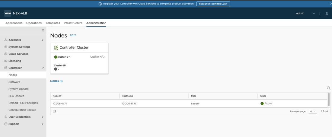
- Navigate to Administration > Controller > Nodes and click the “edit” button.
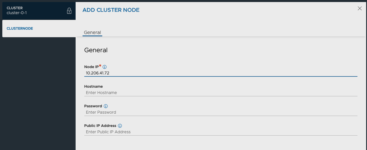
- In the Edit Cluster pop-up window, click the “add” button.

- In the Add Cluster Node pop-up window, provide the IP address and Host Name for one of the new Follower Nodes created in the last section. If you have not set the admin password for the new Node, leave the Password field blank as it will utilize the default password.
- Complete the same process for the second Follower Node created in the last section.
- Once both Follower Nodes have been added to the list, input a Cluster IP (if applicable) and Cluster Name in the designated fields. Cluster name is visible in logs as well as in Customer Connect portal.

- Click Save.
All the Controllers will now restart and form a Cluster. This operation can take up to 10 minutes depending on the speed of underlying infrastructure. Once the operation completes, it is recommended to use the new VIP IP address for any future interaction with the system.
Log back into the system and navigate once again to Administration > Controller > Nodes and validate the state of all 3 Cluster Nodes and HA state are green and Active.

NOTE: If you are going to use IPv6 for the Controller and Cluster Management addresses, navigate to Appendix B. Once completed, return back to this section to complete the remaining steps.
License Configuration
There a several License Tiers available for NSX ALB, however for a vSphere deployment we recommended utilizing the Production Enterprise with Cloud services tier. This License Tier will provide Central Licensesing, Proactive Support and Live Security Threat Intelligence. We recommended contacting a VMware Sales Representative for further details.
The following will outline the steps required to register your Controller Cluster to the NSX ALB Cloud Services.
- In a browser window, Navigate to your Controller Cluster VIP IP or FQDN.
- Login with your admin user.
- Navigate to Administration > Licensing.
-
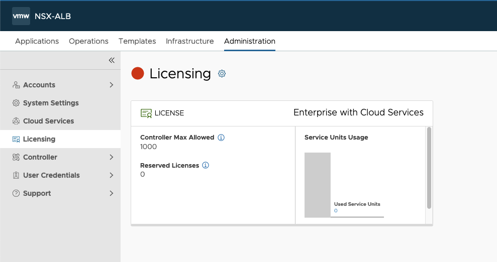
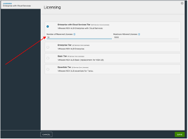
Click the Edit Gear button.
- In the Licensing pop-up window, change the license tier to “Enterprise with Cloud Services Tier”. You can set a License Reservation for this cluster if desired.
- Navigate to Administration > Settings > Cloud Services.
- If your environment requires the use of a proxy to access the internet, click the “EDIT” button.

- In the Cloud Service Settings pop-up window, click the checkbox to enable “Use Cloud Services Split Proxy”, and enter your proxy information.

- Click Save.
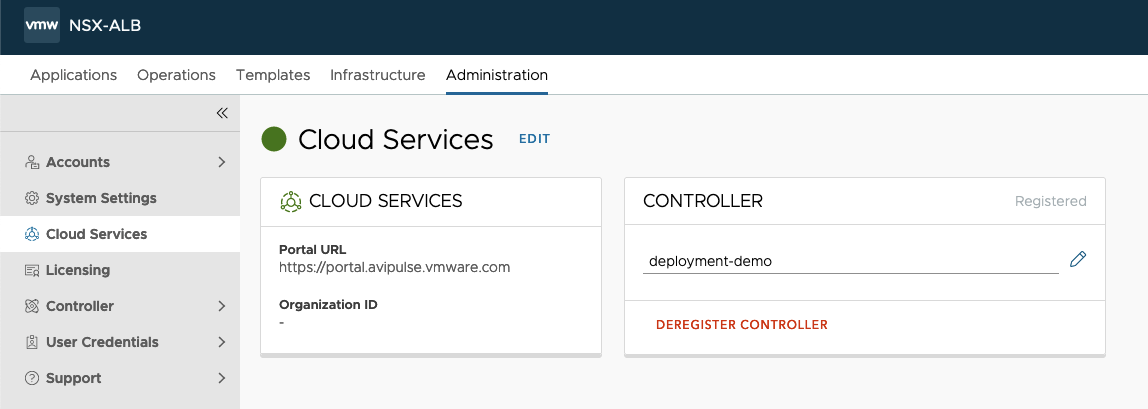
- To register the Controller Cluster, click on “REGISTER CONTROLLER”
- In the Authentication pop-up window, provide credentials used to login to console.cloud.vmware.com and click “Sign In”.

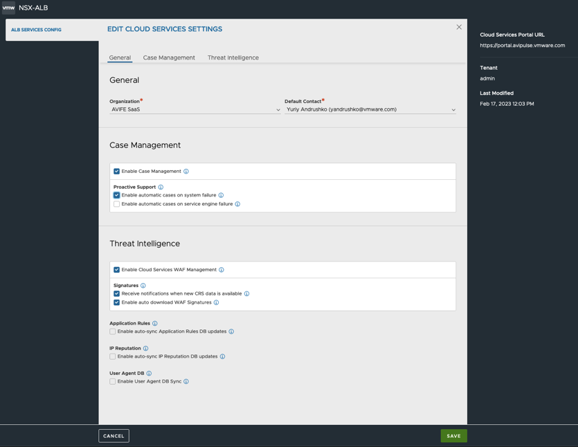
- Once authentication is successful, the browser will be redirected to the Controller UI. Complete the ALB SERVICES CONFIG:
- Select the CSP Organization that you want this Controller Cluster to register against
- Choose the Cloud Service options that are required for your Controller Cluster.
- Click Save.
14. Make sure that Cloud Services is in green state to confirm registration was successful and communication is allowed:
Tenant Creation
A tenant can be configured to isolate load-balanced application configurations on the NSX Advanced Load Balancer. This is an optional configuration which should be chosen depending on the business requirements.
Admins can choose to deploy NSX Advanced Load Balancer in one of three levels of isolation modes with respect to tenancy.
- Provider/ Admin Tenant mode: All the Service Engines and configurations will reside in the ‘admin’ tenant. Provides least isolation.
- Config isolation Tenant mode: All the Service Engines will reside in the ‘admin’ tenant and are shared across the configured Tenants. Configurations will be scoped under each configured Tenant
- Config and Data isolation Tenant mode: The Service Engines as well as configuration will be scoped under each configured Tenant. Provides most isolation.
Furthermore, each tenant may or may not have its own isolated data plane. This will depend on the global configuration of the NSX ALB deployment.
Tenants may be deployed within a Provider Context or a Tenant Context:
- Provider Context mode: Service Engine groups are shared across Tenants.
- Tenant Context mode: Service Engine groups are exclusive to each Tenant.
To configure the Tenant Settings, follow the steps below.
- Navigate to Administration > System Settings > TENANCY MODE.
- Click the “Edit” button.
- In the System Settings pop-up window, click the Tenancy Mode tab to navigate to the Tenant Settings.

- Configure the IP Route Domain and Service Engine Context based on the information provided that best fits the use case for your environment.
- Click Save.
To create a new Tenant and utilize these isolation features, follow the steps below.
- Navigate to Administration > Accounts > Tenants.
- Click Create.In the New Tenant pop-up window, provide the following configuration.
- Name: A name for the Tenant.
- Description: An optional description to outline the use case for the Tenant.
- Tenant Access to Provider Service Engine: Will default to what was defined in the Tenant Settings configured above.
- Tenant VRF: Will default to what was defined in the Tenant Settings configured above.
NOTE: In case per-tenant VRF separation is needed, a VRF will need to be created manually as per section below.

If the new Tenant is to be managed by a separate user, you can create a new Tenant admin (or any other predefined or custom role) by following the steps below.
- Navigating to Administration > Accounts > Users and click Create.
- In the New User pop-up window, provide the following configuration.
- User Status: For new Users, set the status to Active.
- Name: User Full Name
- Username: Name that the user will supply when signing in
- Password: You may either enter a case-sensitive password in this field or click the Generate button to create a random password for the new user.
- Email: Email address of the user. This field is used when a user loses their password and requests to have it reset. See Password Recovery.
- Role: select the areas of the NSX Advanced Load Balancer system to which the user account will be allowed access. For each system area, the role defines whether the user account has read, write, or no access. NSX Advanced Load Balancer comes with predefined roles.
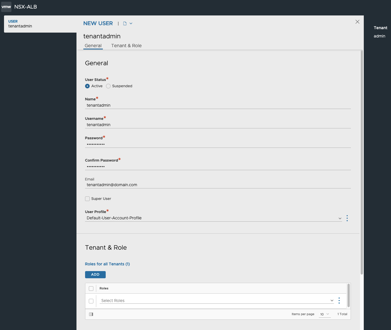
- Click Save.
Configuration Backup
Periodic backup of the NSX ALB configuration database is recommended. This database defines all configured Objects including but not limited to clouds, virtual services, users, policies and profiles . Any user capable of logging into the admin tenant is authorized to perform a backup of the entire configuration, i.e., of all tenants. A restore operation spans all the same entities but can only be performed by the administrator(s) capable of logging into one of the Controllers using SSH or SCP.
It is a best practice to store backups in a safe, external location, in the unlikely event that a disaster destroys the entire Controller (or Controller Cluster), with no possibility of remediation. Based on how often the configuration changes, a recommended backup schedule could be daily or even hourly.
To configure Cluster backup, follow the steps below.
-

Navigate to Administration > Controller > Configuration Backup and click Edit.
-
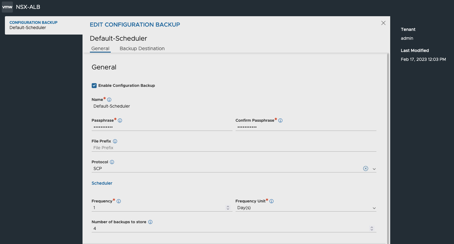
For local-only backup, you only need to specify a Backup Passphrase to encrypt the backup files, the Frequency and the Number of historical backups to store.
- For remote backup, click the check box Enable Remote Server Backup. This will enable additional fields.
- Server Address: The IP or FQDN of the remote Server.
-

Home Directory: The Directory where the Backups will be stored on the remote Server.
-

User Credentials: Click the three dots and choose Create. In the pop-up window specify user credentials where the Name is the remote Server username. Set the Credentials Type to SSH.
- Click Save to finish configuration of Backup.

Changing System Settings
NSX Advanced Load Balancer requires access to valid DNS and NTP (Network Time Protocol) servers for operation. NTP settings are critical for the proper functioning of the Controllers. The analytics functionality in the Controller rely on the fact that the Controller(s) in the cluster and SE(s) are synchronized. Controller(s) synchronize time from the configured NTP servers and the SE(s) in turn synchronize time from the Controller(s).
By default the Controllers are configured with ntp.org NTP servers. If internal NTP servers are required, follow the steps below.
-

Navigate to Administration > System Settings and click Edit.
- Click the DNS/NTP tab, and update the DNS and NTP settings as required.

- Click Save.
For the majority of deployments, the usage of the built-in certificates will be appropriate. If, however, it is required to utilize CA signed certificates for the portal (UI/API endpoint) and/or the Secure Channel (used for SE-to-Controller communication), it is recommended to complete this change before moving further as this process is disruptive in nature.
To import and assign CA signed Certificates, follow the steps below.
- Navigate to Templates > Security > SSL/TLS Certificates and click on Create drop down and select “Controller Certificate”.
- In the New Certificate pop-up window, provide the following information.
- Name: Certificate name.
- Type: Select the type of certificate. To import a CA signed Certificate, select Import.
- Is Federated: Select check box if the certificate needs to be propagated to all GSLB members.
- Import Private Key to HSM: Select check box if the private key needs to be stored on a Hardware Security Module.
- Certificate File: Import the Certificate file or copy-paste the content into the designated field.
- Key File: Import the Key file or copy-paste the content into the designated field.
- Click Validate to validate the imported Certificate content.
-

Once the validation is completed, click Save.
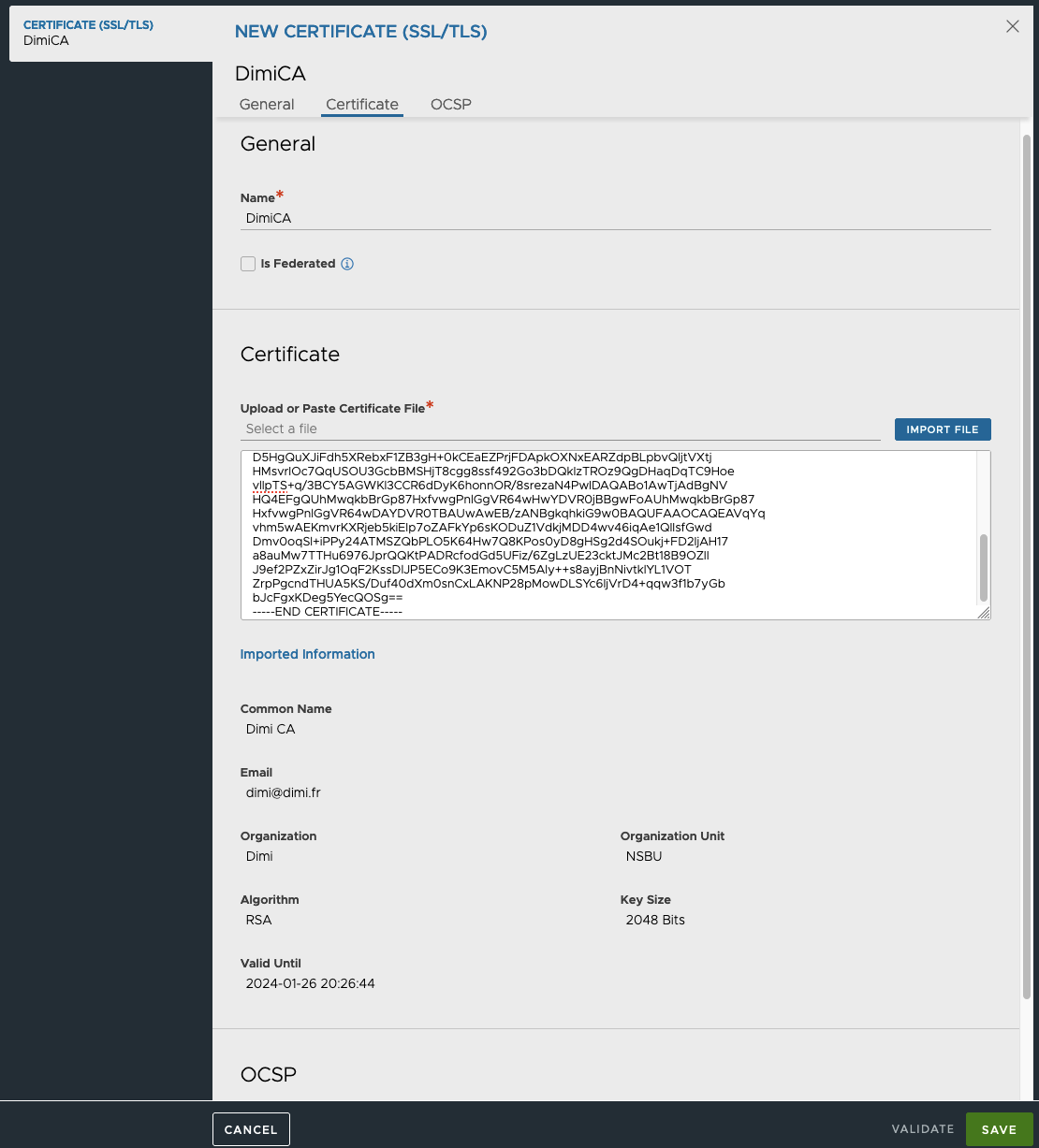
If the imported certificate lacks the CA/chain certificates, we will need to manually import the Root Certificate, by following the steps below.
- Click the Create drop-down and choose “Root/Intermediate CA Certificate”.
- In New Certificate window, and provide the following information.
- Name: Certificate Name
- Is Federated: Select check box if the certificate needs to be propagated to all GSLB members.
- Certificate File: Import the Certificate file or copy-paste the content into the designated field.
- Click Validate to validate the imported Certificate content.
- Once the validation is completed, click Save.
Once the Certificates have been imported, the certificate status should turn green. To change the Portal or Secure Channel certificate, follow the steps below.
- Navigate to Administration > System Settings and click Edit.
- Click the Access tab.
- To change the Portal Certificate, remove the configured Certificates under “SSL/TLS Certificate” and add the newly created certificate. The UI session will restart and new certificate will be presented.
- To change the Secure Channel Certificate, remove the configured Certificates under “Secure Channel SSL/TLS Certificate” and add the newly created certificate.

NOTE: If the Secure Channel Certificate (SE to Controller Cluster communication) needs to be changed, it is recommended to make this change before a Cloud is configured. Otherwise, all deployed SEs will need to be deleted and Cloud reconfigured.
Cloud Creation
NSX ALB provides a Default-Cloud that can be converted to any Cloud type. The Default-Cloud is recommended for small footprint deployments, where there are no plans to utilize additional Clouds in the future. However, the Default-Cloud cannot be renamed. For the majority of deployments, VMware recommends creating a new Cloud object. To create a new Cloud deployment, follow the steps below.
- Navigate to Infrastructure > Clouds, click the Create dropdown list and choose “VMware vCenter/vSphere ESX”.
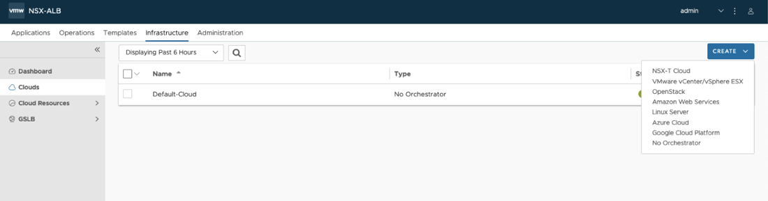
- In the New Cloud pop-up window, provide the following information.
- Name: Cloud name.
- Object Name Prefix: Default prefix for all automatically created objects in this Cloud.
- Template Service Engine Group: Leave empty as we will be defining a new SE Group later.
- Enable DHCP: Click the check box if you DHCP will be used for the Data Segments.

- Prefer Static Routes vs Directly Connected Network: Click the check box to turn SE into one arm mode and prevent adding additional NICs for backend Networks.
- Use Static Routes for Network Resolution of VIP: Click the check box to use static Routes for VIP side network resolution during VS placement.
- To configure the vCenter connection, click Set Credentials and provide the following information.
- vCenter Address: The IP or FQDN of the vCenter Server
- Username: The vCenter user. It is recommended to not utilize the adminsitrator@vsphere.local user, and create a customer user with the roles and permissions defined in Appendix A.
- Password: The vCenter user password.
-

Access Permission: Write.
- Click Connect. If authentication was successful, vCenter inventory will be discovered.
- Choose the desired Datacenter from drop-down.
- If the vCenter networking is integrated with NSX-T and there are segments spanning multiple VDSes, select “Managed by NSX Environment”. This will combine segments with the same name on different VDSes into single Network object.
- VMware recommends using Content Library for SE image storage.
- Click Save and Relaunch.

- Once the refresh is completed, proceed with choosing the SE Management Network.
- If the SE Management Network utilizes DHCP, select the Enable DHCP check box.

- If desired, you can configure tags for objects created by this Cloud Connector. To do so, scroll down to the bottom of the screen and the desired tags.

VRF Creation
Depending on the need for traffic separation in Per-Tenant IP Routing Domain mode, which is discussed above, you can create additional VRFs by following the steps below.
- Navigate to Infrastructure > Cloud Resources > VRF Context.
- Select the appropriate Cloud from drop-down list and press Create button.
- In the Create VRF Context window, provide the following information.
- Name: A name for the VRF Context
- Bidirectional Forwarding Detection (BFD): To enable networking peers on each end of a link to quickly detect and recover from a link failure.
- Detection Multiplier: Default Detection Multiplier used in BFD.
- Minimum Transmit Interval: Default Minimum Transmit Interval (in ms) used by BFD.
- Minimum Receive Interval: Default Minimum Receive Interval (in ms) used by BFD.
- Static Route: Click ADD to add a static route for the VRF Context. Enter the Gateway Subnet and the Next Hop for any traffic matching the IP subnet to be sent to the IP address of the next hop gateway.
- Click Save.

NOTE: Configuring BGP peering is outside the scope of this guide.
IPAM and DNS Profiles
The basic Cloud configuration is now complete; however, it is recommended to utilize IPAM and DNS profiles to automate the VIP IP and FQDN configuration. Before saving the Cloud configuration, we can setup these profiles from the Cloud Creation pop-up window.
To create and associate an IPAM profile, follow the steps below.
- Press three dots by IPAM Profile and click Create. Give the profile a name and specify its type. Configuring IPAM types other than Avi Vantage IPAM (native NSX ALB type) is outside the scope of this guide. Please, refer to documentation found on our website for configuration guides of other IPAM types.

- In case VRFs are employed (i.e. Tenant-dedicated IP Routing Domain), check "Allocate IP in VRF ".
- Choose a newly created Cloud
- Click the Add button to add usable networks.
-
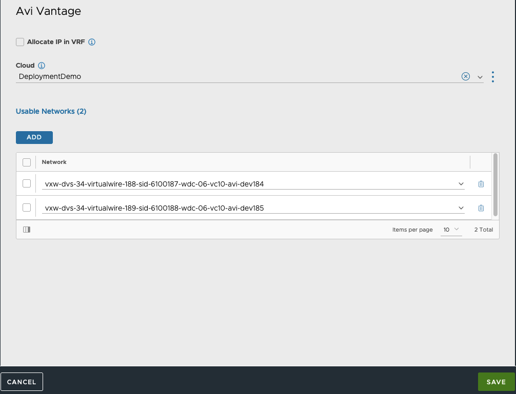
Click Save.
To create and associate an DNS profile, follow the steps below.
- Press three dots by DNS Profile and choose Create. Give the profile a name and choose the type of DNS profile. Configuring DNS types other than Avi Vantage DNS (native NSX ALB type) is outside the scope of this guide. Please, refer to documentation found on our website for configuration guides of other IPAM types.
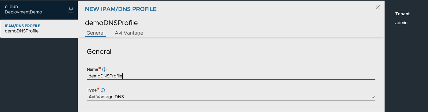
- Enter a delegated subdomain(s) and, optionally, modify default TTL value

- Click Save.
- In the Cloud configuration screen, click Save to update the Cloud configuration.
Routing Configuration
For Cloud Networks that do not utilize DHCP, the Default Gateway is not defined which may or may not be a problem in specific situations. If, for example, the Management interface is associated to the same VDS Portgroup as the Controller Nodes, then a Default Gateway or routing configuration is usually not needed.
For Application Delivery Controller (ADC) related traffic, the lack of a Default Gateway is usually compensated for by having the “Autogateway” feature enabled during VS configuration. However, in the case where SE DNS resolution is configured and the DNS resolver is residing outside of the local network, Routing Configuration will still be needed.
Important to note that even without Tenancy, each Cloud will have at least two separate VRFs – “management” and “global” – for management and data traffic respectively. Note that these VRFs are naturally belong to “admin” tenant and are Cloud-specific. For the global VRF and custom VRFs, the Routing configuration are accessible via the UI, while the configuration elements for the management VRF are accessible via CLI only.
To configure routing via CLI, follow the steps below.
- Open an SSH session to Controller Cluster’s VIP using the admin credentials.
- Type “shell” in the command prompt and provide the “admin” credentials.
ssh admin@CLUSTERVIP
admin@10-206-41-71:~$ shell
Login: admin
Password:
- From inside NSX ALB CLI, access the VRF in question (management in this example).
- From the Cloud list, select the desired target Cloud.
- Access the static routes configuration sub mode and configure the Default Route.
- Provide the Next_hop ip address
- Provide the destination Network prefix (for the Default Gateway specify 0.0.0.0/0)
- Save the Route configuration and VRF configuration.
[admin:10-206-41-71]: > configure vrfcontext management
Multiple objects found for this query.
[0]: vrfcontext-e9969d75-b901-4811-ae7c-1194914fc0a9#management in tenant admin, Cloud Default-Cloud
[1]: vrfcontext-fe7b4649-2cd2-4824-b3cf-c5eb40712863#management in tenant admin, Cloud DeploymentDemo
Select one: 1
[admin:10-206-41-71]: vrfcontext> static_routes
New object being created
[admin:10-206-41-71]: vrfcontext:static_routes> next_hop 10.206.40.1
[admin:10-206-41-71]: vrfcontext:static_routes> prefix 0.0.0.0/0
[admin:10-206-41-71]: vrfcontext:static_routes> save
[admin:10-206-41-71]: vrfcontext> save
- Configure any outstanding routes for custom VRFs as per your deployment.
NOTE: If IPv6 is used for SE-Controller communication, refer to Appendix B for further information about route configuration.
Usable Networks Setup
Now that we have the Cloud configured with an IPAM profile, we need to configure the associated Networks to allow for autoconfiguration of the VS VIP addressing and SE interfaces. For both Management and data interfaces, DHCP is a preferred solution as it eliminates the need for static route configuration. If DHCP is not available, then IP Pools should be used, however routes may need to be configured for the associated VRF context.
If the networks that were configured in the IPAM profile do not have DHCP support, then follow the steps below to configure IP Pools.
- Navigate to Infrastructure > Cloud Resources > Networks and select the new Cloud from drop-down list.
- The list of networks (VDS segments) will be retrieved. You can use the search icon in the top right corner of the list to narrow down the displayed networks.
- On the desired network, click the pencil button to edit the network settings.
- In the Edit Network Settings pop-up window, unselect Enable DHCP.

- During the Cloud inventory process, the discovered subnets will be populated. If the inventory process does not find any subnets for the specific network, a new subnet can be added by clicking the ADD button.
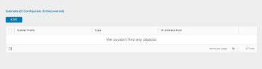
- In the Add Subnet pop-up window, specify the subnet prefix.
- Click the ADD button to specify the IP Pool range.
- If the IP Pool is to be used for both VS VIP and SE interface configurations, then leave the configuration as is. If your configuration will have dedicated ranges for VS VIP and SE interfaces, then un check Use Static IP Address for VIPs and SE, and specify the usage for each defined IP Pool range.
- If the inventory process does discover subnets, the same process can be done to add the IP Pool configuration, by clicking the pencil button.
- In the Edit Subnet pop-up window, validate the subnet prefix.
- Click the ADD button to specify the IP Pool range.
-

If the IP Pool is to be used for both VS VIP and SE interface configurations, then leave the configuration as is. If your configuration will have dedicated ranges for VS VIP and SE interfaces, then uncheck Use Static IP Address for VIPs and SE and specify the usage for each defined IP Pool range.
- Click Save.
- Back in Edit Network Settings window, you can optionally check “Exclude Discovered Subnets for Virtual Service Placement” box to force this manual binding between VDS segment and configured VIP subnet - for example when you’d like to have a separate VIP network, but data NICs should still derive their IPs from discovered subnet. Click “Save”
To complete the Cloud configuration, you should have at least two networks configured (with IP Pools or DHCP) – one designated as Management network (provided during Cloud configuration) and one for data traffic.
NOTE: If DHCP is available for the network subnet, it can only be used for automating the SE interface IP addressing. An IP Pool will need to be configured for use for VS VIPs.
SE Group Configuration
Service Engines are created within a group, which contains the definition of how the SEs should be sized, placed, and made highly available. Each cloud will have at least one SE group. SEs may only exist within one group. Each group acts as an isolation domain. SE resources within an SE group may be moved around to accommodate virtual services, but SE resources are never shared between SE groups.
Multiple SE groups may exist within a cloud. A newly created virtual service will be placed on the default SE group, though this can be changed via the VS > Advanced page while creating a VS via the advanced wizard. To move an existing virtual service from one SE group to another, the VS must first be disabled, moved, and then re-enabled. SE groups provide data plane isolation; therefore moving a VS from one SE group to another is disruptive to existing connections through the virtual service.
To create a new Service Engine Group and configure basic settings, follow the steps below.
- Navigate to Infrastructure > Cloud Resources > Service Engine Group and select the new Cloud from drop-down list.
- click Create.
- In the New Service Engine Group pop-up window, provide the following information.
- Name: Service Engine Group name
- Enable Real time Metrics: Click check box to turn on real-time metrics, which will cause SEs in the group to upload SE-related metrics to the Controller once every 5 seconds, as opposed to default of 5 minutes. After clicking the box, select the duration in minutes for real-time updating to last. A value of 0 is interpreted to mean “forever.”
-

Enable Per-app Service Engine Mode: Click check box if the SEG will server a max VS of 2. vCPUs in per-app SEs count towards licensing at 25% rate.
- High Availability Mode: Select the appropriate HA mode to control the behavior of the SE group in the event of an SE failure. The 3 available options are:
- Legacy HA Active/Standby Mode — This mode is primarily intended to mimic a legacy appliance load balancer for easy migration to NSX ALB. Only two Service Engines may be created. For every virtual service active on one, there is a standby on the other, configured and ready to take over in the event of a failure of the active SE. There is no Service Engine scale out in this HA mode.
- Elastic HA N + M Mode — This default mode permits up to N active SEs to deliver virtual services, with the capacity equivalent of M SEs within the group ready to absorb SE(s) failure(s).
- Elastic HA Active/Active Mode — This HA mode distributes virtual services across a minimum of
two SEs.
NOTE: The recommended HA Mode is N+M as it provides the most reliability and scalability for the deployed Virtual Services.
- Number of Service Engines: Define the maximum number of Service Engines that may be created within a Service Engine group. The default is 10 but can be increased any time.
- Buffer Service Engines: Specify the number of VMs that are deployed to ensure excess capacity in the event of a failover.
- Virtual Services per Service Engine: The maximum number of virtual services the Controller cluster can place on any one of the Service Engines in the group. The default is 10 and maximum is 100, however VMware recommends limiting VS placement counts.
- Virtual Service Placement Across Service Engines: Select Distributed. Selecting this option maximizes the performance by placing virtual services on newly spun-up Service Engines up to the maximum number of Service Engines specified. Default is Compact.
- Scale per Virtual Service: Specify the minimum and maximum number of Active SE for each VS. With native SE scaling, the maximum is 4, with BGP-based SE scaling, the limit can be higher. We recommend setting the minimum count to at least 2, in the case of SE failure or during Upgrade events, VS will not experience impact.

Service Engine Groups also allow the end user to configure vSphere Host and Datastore settings, as well as SE VM resource settings. For a full list of Service Engine Group settings and advanced configuration settings, please refer to the links below.
SE Configuration Guide - https://avinetworks.com/docs/22.1/service-engine-group/
SE Sizing - https://avinetworks.com/docs/latest/nsx-alb-performance-datasheet/
Appendix A - Summary of User Permissions
The following is a breakdown of the required Roles and permissions that are required for the vSphere Cloud User. For further details, please refer to the following link - https://avinetworks.com/docs/latest/vmware-user-role/.
NSX ALB Global Role Privileges:
Content Library
- Add library item
- Delete library item
- Update files
- Update library item
Datastore
- Allocate space
- Remove file
Network
- Assign network
- Move network
Resource
- Assign virtual machine to resource pool
vApp
- Import
Virtual machine
- Change Configuration
- Add new disk
- Advanced configuration
NSX ALB Folder Role Privileges
dvPort group (All)
- Create
- Delete
- IPFIX operation
- Modify
- Policy operation
- Scope operation
Distributed switch
- Create
- Host operation
- Modify
- Network I/O control operation
- Policy operation
- Port configuration operation
- Port setting operation
Datacenter
- Network protocol profile configuration
- Query IP pool allocation
- Release IP allocation
Datastore
- Allocate space
- Browse datastore
- Configure datastore
- Low level file operations
- Remove file
- Update virtual machine files
- Update virtual machine metadata
Folder
- Create folder
Host
- CIM
- CIM interaction
- Configuration
- Change settings
- Hyperthreading
- Image configuration
- Memory configuration
- Network configuration
- Power
- System Management
- System resources
- Virtual machine autostart configuration
- Inventory (all)
- Add host to cluster
- Add standalone host
- Create cluster
- Manage Cluster Lifecyle
- Modify cluster
- Move cluster or standalone host
- Move host
- Remove cluster
- Remove host
- Rename cluster
- Local operations (all)
- Add host to vCenter
- Create virtual machine
- Delete virtual machine
- Manage user groups
- Reconfigure virtual machine
Network (all)
- Assign network
- Configure
- Move network
- Remove
Performance (all)
- Modify intervals
Resource
- Assign virtual machine to resource pool
Tasks (all)
- Create task
- Update task
vApp (all)
- Add virtual machine
- Assign resource pool
- Assign vApp
- Clone
- Create
- Delete
- Export
- Import
- Move
- Power off
- Power on
- Pull from URL
- Rename
- Suspend
- Unregister
- View OVF environment
- vApp application configuration
- vApp instance configuration
- vApp managedBy configuration
- vApp resource configuration
Virtual machine (all)
- Change Configuration
- Acquire disk lease
- Add existing disk
- Add new disk
- Add or remove device
- Advanced configuration
- Change CPU count
- Change Memory
- Change Settings
- Change Swapfile placement
- Change resource
- Configure Host USB device
- Configure Raw device
- Configure managedBy
- Display connection settings
- Extend virtual disk
- Modify device settings
- Query Fault Tolerance compatibility
- Query unowned files
- Reload from path
- Remove disk
- Rename
- Reset guest information
- Set annotation
- Toggle disk change tracking
- Toggle fork parent
- Upgrade virtual machine compatibility
- Edit Inventory
- Create from existing
- Create new
- Move
- Register
- Remove
- Unregister
- Guest operations
- Guest operation alias modification
- Guest operation alias query
- Guest operation modifications
- Guest operation program execution
- Guest operation queries
- Interaction
- Answer question
- Backup operation on virtual machine
- Configure CD media
- Configure floppy media
- Connect devices
- Console interaction
- Create screenshot
- Defragment all disks
- Drag and drop
- Guest operating system management by VIX API
- Inject USB HID scan codes
- Install VMware Tools
- Pause or Unpause
- Perform wipe or shrink operations
- Power off
- Power on
- Record session on virtual machine
- Replay session on virtual machine
- Reset
- Resume Fault Tolerance
- Suspend
- Suspend Fault Tolerance
- Suspend to memory
- Test failover
- Test restart Secondary VM
- Turn off Fault Tolerance
- Turn on Fault Tolerance
- Provisioning
- Allow disk access
- Allow file access
- Allow read-only disk access
- Allow virtual machine download
- Allow virtual machine files upload
- Clone template
- Clone virtual machine
- Create template from virtual machine
- Customize guest
- Deploy template
- Mark as template
- Mark as virtual machine
- Modify customization specification
- Promote disks
- Read customization specifications
- Service configuration
- Allow notifications
- Allow polling of global event notifications
- Manage service configurations
- Modify service configuration
- Query service configurations
- Read service configuration
- Snapshot management
- Create snapshot
- Remove snapshot
- Rename snapshot
- Revert to snapshot
- vSphere Replication
- Configure replication
- Manage replication
- Monitor replication
Appendix B - IPv6 for Controller-SE Communication
Starting with NSX Advanced Load Balancer version 22.1.3 release, you can add mode6, ip6, and gateway6 instead of mode, IP, and gateway for the IPv6 interface. The interface configuration does not support dual-stack mode in 22.1.3. Hence, an interface can have either a V4 IP or a V6 IP, not both.
The SE_SECURE_CHANNEL label could be moved to the secondary interface to enable communication to Service Engines. This secondary interface could be either of IPv4 or IPv6. This would help users to have different interfaces for management and Service Engine communication.
Sample configuration steps to configure IPv6 interface with SE_SECURE_CHANNEL label attached to IPv6 interface is as shown below:
ssh admin@CLUSTERVIP
shell
configure cluster
nodes index 1
interfaces index 1
no labels SE_SECURE_CHANNEL
save
interfaces index 2
labels SE_SECURE_CHANNEL
mode6 STATIC
ip6 2402:740:0:40e::20:3/128
save
static_routes
prefix ::/0
next_hop 2402:740:0:40e::20:1
if_name eth1
route_id 1
save
save
nodes index 2
interfaces index 1
no labels SE_SECURE_CHANNEL
save
interfaces index 2
labels SE_SECURE_CHANNEL
mode6 STATIC
ip6 2402:740:0:40e::20:4/128
save
static_routes
prefix ::/0
next_hop 2402:740:0:40e::20:1
if_name eth1
route_id 1
save
save
nodes index 3
interfaces index 1
no labels SE_SECURE_CHANNEL
save
interfaces index 2
labels SE_SECURE_CHANNEL
mode6 STATIC
ip6 2402:740:0:40e::20:5/128
save
static_routes
prefix ::/0
next_hop 2402:740:0:40e::20:1
if_name eth1
route_id 1
save
save
save
For further details, please refer to the following KB article -
https://avinetworks.com/docs/latest/controller-interface-and-route-management