
Stateful Active/Active Gateways
Introduction
By definition, a stateful service maintains a context, or a “state,” for the traffic it is dealing with. To maintain the state, the service must be able to view both directions of a flow. This requirement is typically not met when a gateway is implemented using multiple active service routers (SRs), as illustrated in the following diagram:
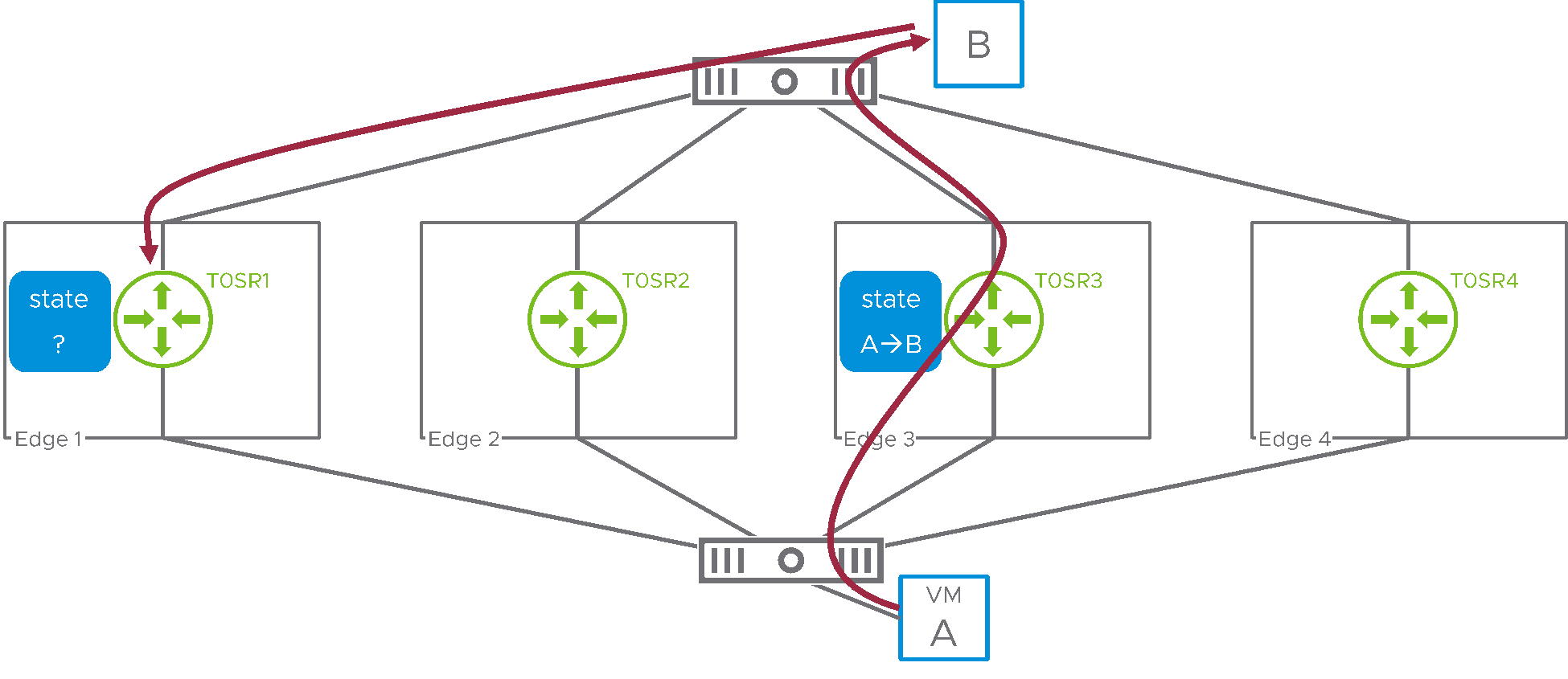
Figure 1: stateful service and A/A service routers
Here, VM A (attached to an NSX overlay segment) is establishing a connection to a physical host, labeled B. Northbound traffic is routed through T0SR3 on edge3. However, because of ECMP in the physical network, the return traffic from B to A is presented to T0SR1, on edge1. This SR therefore cannot determine the state for the flow initiated by A and the stateful service cannot be performed.
NSX solves this issue by requiring that gateways that host stateful services run in active/standby mode. With this redundancy model, a single SR is responsible for forwarding all the traffic, and it can therefore see both directions for all flows.
That said, in some scenarios, it is desirable to scale out the number of edges forwarding traffic while running stateful services, meaning that we need to make the topology described in Figure 1 work. NSX 4.1 introduces the capability of running stateful active/active gateway for this purpose. This white paper describes the implement a high level. It also explains its design implications.
Stateful Active/Active Gateways Technical Overview
When running a gateway in active/active mode, multiple SRs are active for the gateway. As we saw in Figure 1, ECMP in NSX and the physical infrastructure make it impossible to predict which SR is going to receive the packet for a given flow. It is not scalable to synchronize the state for all services in real time across all active SRs, so the solution is to redirect flows so that their traffic hits the same SR consistently in both directions. We’ll also see the impact this model has on redundancy.
Redirecting traffic to the appropriate SR
The following diagram introduces the additional switching infrastructure that was added to NSX to allow the redirection of traffic to the appropriate SR.
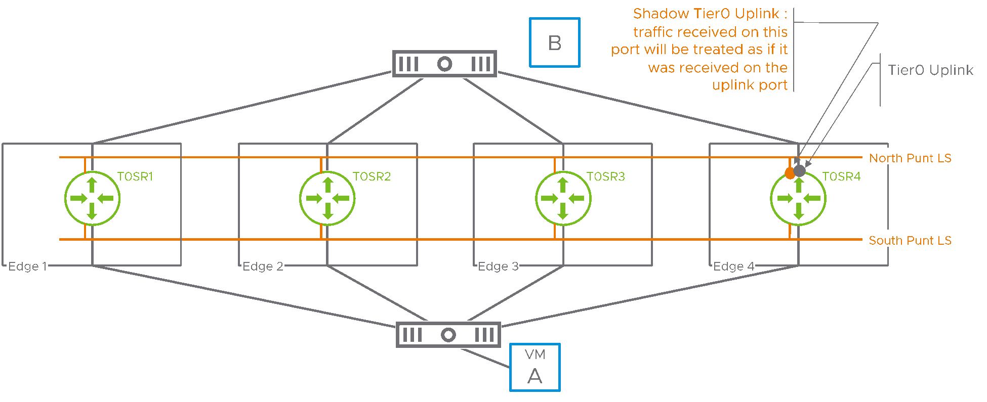
Figure 2: punt logical switches
The Tier0 represented in Figure 2 is running in a stateful active/active mode. Its SRs are spread across four different edges. NSX has created two “punt” logical switches and each SR is attached to those two logical switches with a shadow port. In the above example, the shadow port of SR4 connecting to the north punt logical switch is highlighted. SR4 will treat traffic received on this shadow port as if it had been received on the Tier0 uplink of SR4. A similar shadow port connects SR4 to the south punt logical switch. Traffic received on this shadow port will be treated as if it had been received on the internal port (sometimes referred to as the “backplane port”) connecting SR4 to other distributed routers (DRs).
This additional switching infrastructure will be used to redirect traffic for a specific flow to a deterministic SR. The following Figure 3 illustrates how this is achieved in the “northbound” direction. VM A sends traffic towards B and the ECMP router inside NSX forwards the packets of this flow to T0SR3, on edge3.
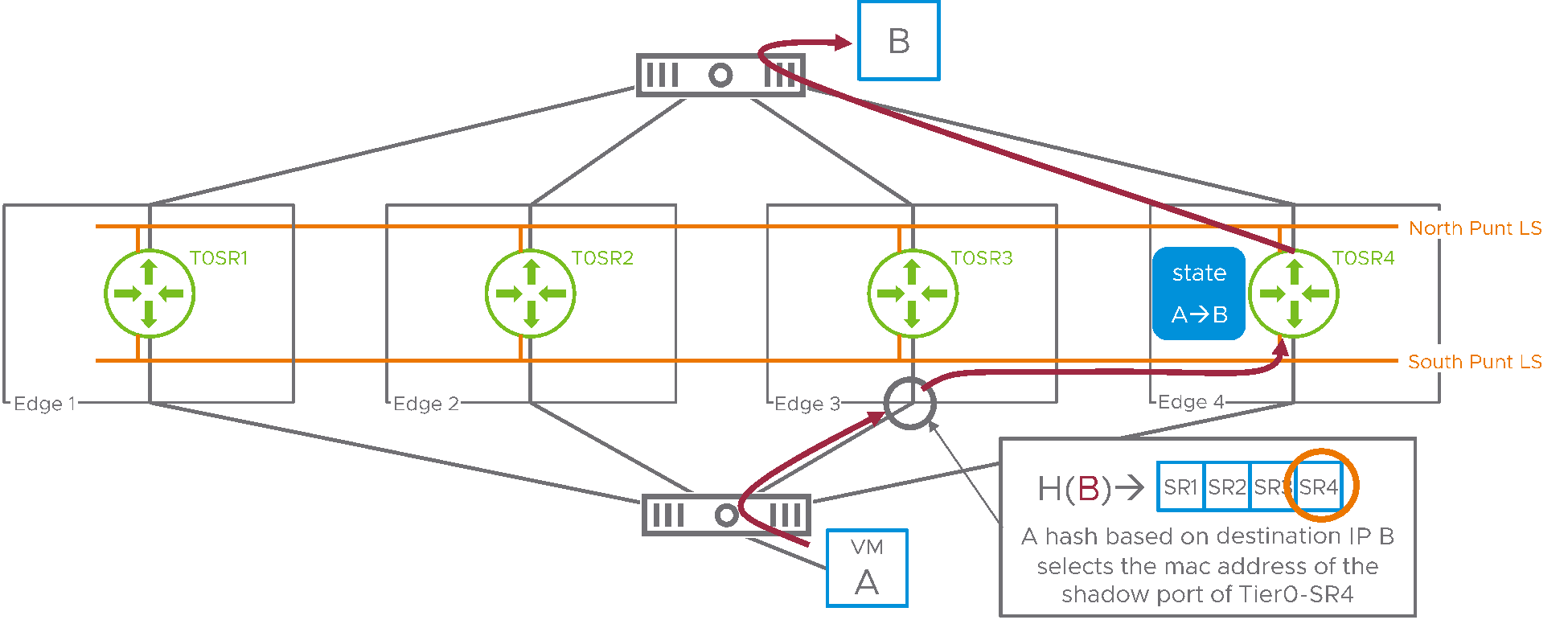
Figure 3: northbound traffic
When edge3 receives this packet from A, a hash is calculated based on the destination IP address of the traffic. The resulting value is used as an index that selects SR4 in a table including all the SRs for the Tier0 gateway. Edge3 uses the south punt logical switch to switch the packet to the shadow port on SR4. Here, SR4 treats this packet as it had been received on its backplane port and routes it directly to its destination. Any packet flowing to destination IP address B will be redirected to SR4 with this model. Of course, the same mechanism is applied in the southbound direction, as represented in the next diagram.
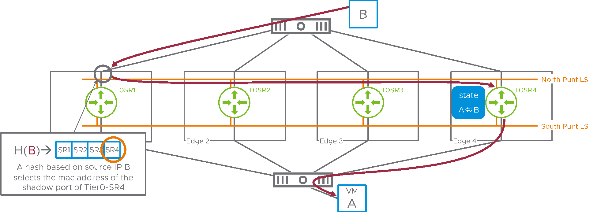
In Figure 4, host B replies to VM A. Its packets are routed by the physical infrastructure to an arbitrary active SR, here SR1. When entering SR1, a hash is taken on the source IP address this time. This allows selecting the same SR in the table as the one that was selected using the destination IP address in the northbound direction. SR1 immediately switches those packets on the northbound punt logical switch to the shadow port on SR4, where it’s accepted as if they had been received on SR4 uplink.
This example is of course a worst-case scenario where traffic needs to be redirected in each direction. Still, thanks to scaling out to four active SRs, the overall forwarding capability into and out of NSX is greatly enhanced compared to a single active SR.
Active/Active Tier1 gateways
So far, we have only represented active/active Tier0 gateways, with uplinks pointing to the physical infrastructure. The new active/active stateful gateways feature also enables active/active stateful Tier1 gateways. NSX typically provides great flexibility in the deployment of Tier1 SRs. They could be on a dedicated edge cluster, for example, and the user can explicitly designate on which edges active and standby SRs will be located. Active/active stateful Tier1 gateways will only run in the very specific configuration where they share their edges with a corresponding active/active Tier0 gateway, as represented below:
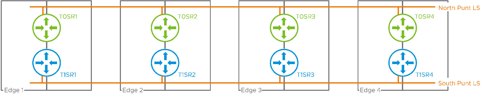
Figure 5: active/active stateful Tier1 gateway
This model simplifies redundancy . By sharing the fate of the Tier1 SR and the Tier0 SR, it also allows using the same pair of north/south punt logical switches for both gateways.
Redundancy model
The hashing mechanism ensures that a given flow always hits the same SR. But what if this SR goes down? In that case, the state associated to the flow must be saved continuously to the SR that will take over for the failed one. To achieve that, NSX automatically splits the edge cluster into sub-clusters, with each sub-cluster comprising two edges. Edges in the same sub-cluster sync their state and serve as backups to each other. Of course, for this model to work properly, the feature expects an even number of edges in the cluster.
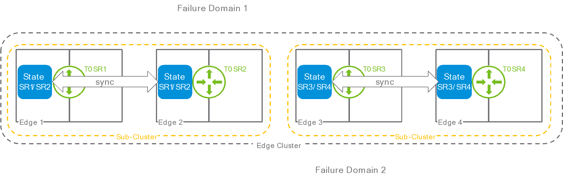
Figure 6: sub-clusters
The user cannot explicitly select which edge is part of a sub-cluster, but NSX attempts to group sub-clusters edges from different failure domains.
Implication on Consumption and Design
SRs have identical connectivity
When a service is configured on an active/standby gateway, it is obvious that the active SR must be capable of providing this service. The same applies to a stateful active/active gateway with multiple active SRs. Traffic can be arbitrarily distributed across all the SRs of that gateway. As a result, each SR is supposed to have the capability of providing the service. If the service is bound to a specific uplink or service interface, this uplink or service interface must be instantiated on each SR.
Interface groups
In Figure 4, we could see that traffic received on an uplink of SR1 could be re-injected into SR4 as if it had been received on the uplink of SR4. But what if SR4 had multiple uplinks? Suppose that the Tier0 had two uplinks, one connecting to the Internet, and one leading to a DMZ. The administrator configures SNAT, a stateful service, for the traffic toward the Internet only. When the traffic for a flow subject to SNAT is received on the “Internet” uplink of SR1 and redirected to SR4, how can NSX identify which of the two uplinks of SR4 correspond to the connection to the Internet? There is no obvious relation between the “Internet” uplink of SR1 and the “Internet” uplink of SR4; they can be in completely different subnets. The administrator must thus provide this information explicitly, by grouping uplinks and service interfaces into “interface groups.”
The following example represents the two interface groups that would be required when having separate uplinks going to the Internet and to a DMZ:
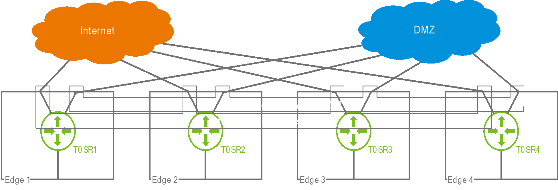
Figure 7: interface group
When using a stateful active/active Tier1, an internal group representing the connectivity between the Tier1 and the Tier0 is automatically created by the system.
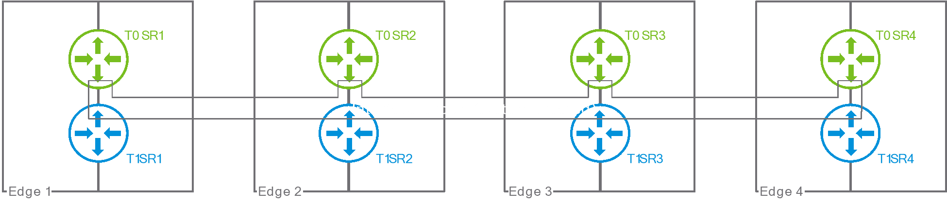
Figure 8: auto-created interface group between Tier1 and Tier0
Design constraints
When a Tier0 is configured as stateful active/active, design options for connected Tier1s exist. Suppose that a stateful active/active has its SRs deployed on an edge cluster. A Tier1 connected to this Tier0 can be:
- Distributed only, meaning that it has no SR and can’t run stateful services.
- Stateful active/active, meaning its SRs must be deployed on the same edge cluster as the Tier0. The Tier1 SRs will end up running on the exact same edges as the Tier0 SRs.
- Active/standby, and its SRs must be deployed in a separate cluster from the Tier0.
The following table represent all the possible SR placement combinations for a Tier1 connected to a Tier0, including those that are not supported:
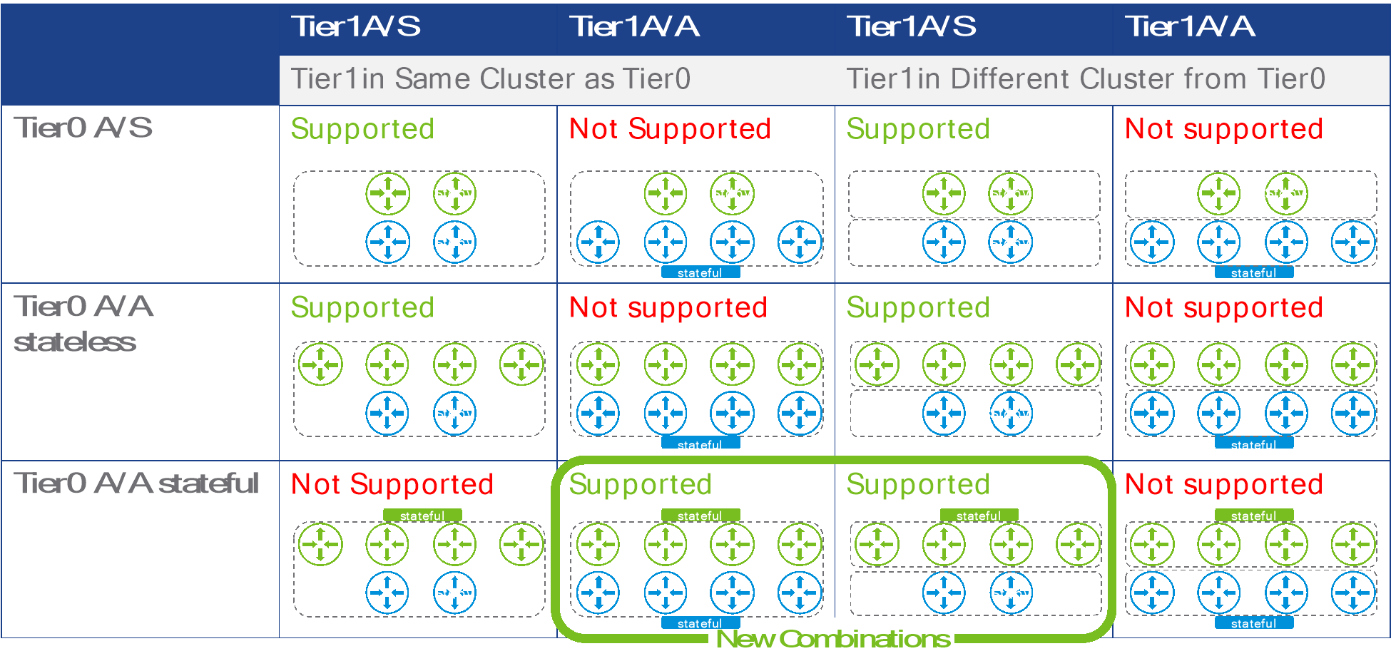
Figure 9: possible SR placements for Tier0 and Tier1
Introducing a stateful active/active gateway in an existing environment is subject to the following rules:
- An active/standby Tier0 cannot be converted to stateful active/active.
- An active/standby Tier1 cannot be converted to stateful active/active.
- A stateless active/active Tier0 with no attached Tier1 can be converted to stateful active/active.
The possible steps for introducing stateful active/active gateways are represented in the following diagram:
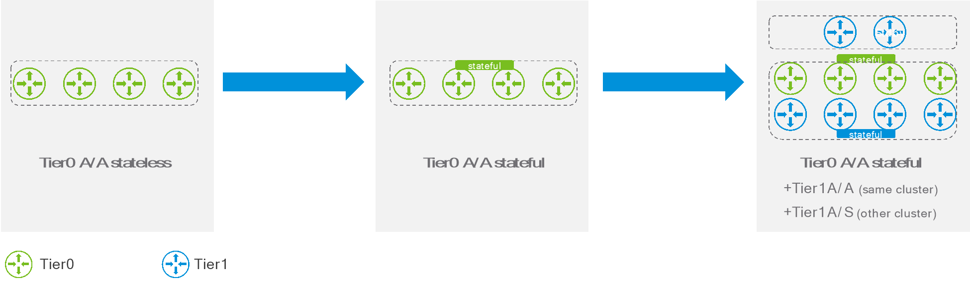
Figure 10: Introducing stateful active/active gateways.
Performance considerations
The drawback with the stateful active/active model is the additional overhead introduced by redirecting traffic on the punt logical switches. If ECMP routing distributes the traffic evenly across N edges, roughly (1/N) % of the traffic received by an edge will not be redirected. You can see that this percentage, and thus the efficiency of the model, will decrease as the number of edges involved increases. But even in a worst-case scenario where all the traffic is redirected, the model would provide the aggregate bandwidth of N/2 edges for traffic in and out of NSX. This beats running a single stateful edge all the time, and it scales out linearly with the number of edges.
Supported features
Be aware that not all stateful services can be deployed on a stateful active/active edge. Please be consult the release notes for the NSX version you are intending to deploy in your environment for an updated list of features that are compatible with stateful active/active gateway.