
NSX Easy Adoption Design Guide
1 Introduction
1.1 Scope of the document
VMware NSX is a full-stack Software-Defined Networking and Security offering from VMware. It contains L2 through L7 network and security services designed to meet the needs of small two-node development or proof of concept deployments all the way to highly regulated global enterprises and Service Providers or mega cloud providers. This solutions guide is not intended for massive service providers and Global Enterprises.This guide is actionable for small to medium-sized deployments that fall into two specific use cases:
- A simplified security solution designed for existing workloads where the physical network retains many networking functionalities.
- A full-stack design that primarily targets new deployments minimizing interaction with the external network while providing extensive flexibility and Network and Security services inside the solution.
The solutions presented focus on the following goals and parameters:
- Physical network-friendly configuration – minimum configuration
- Leverage existing knowledge base from vSphere and Security Admin
- Exploit the features and capabilities from NSX to build a flexible yet consolidated solution for a variety of application needs, services (NAT, VPN, FW, LB) and security
- Scope of deployment meeting most common footprint for small workload, satellite DC, and hosted solutions:
- The number of Hosts is as small as two and as large as 50
- Single vSphere Cluster deployment model
- Total number of virtual machines is less than 1000
- All hosts connect to a single pair of switches (usually in a single rack)
- Existing infrastructure level services already exist and are reachable (e.g., NTP, DNS, LDAP/AD, etc.)
The minimum NSX software version to implement the solutions described in this document is NSX 3.1.3. Later versions have not been validated but should be compatible with the two use cases in scope.
Due to their specific audience, the solutions presented in this document make some compromises in the interest of simplicity for implementation and operations at the expense of optimizing performance and handling compound failure scenarios. If these trade-offs are not palatable, we recommend that this guide be used as a starting point for a customized solution or leverage VMware Cloud Foundation, which includes NSX as a core component.
1.2 How to use this document
This document incorporates two main sections. Each of them addresses the two use cases at a different level.
Section 2 covers a high-level overview of the two solutions, together with their value proposition in the context of well-defined requirements and constraints. We also include a brief overview of the relevant NSX components.
Section 3 provides a detailed design and engineering specification for both use cases. It includes a comprehensive list of assumptions on the supporting infrastructure. Design decisions have accompanying justifications and implications for making the designs actionable and the rationale behind the choices clear and transparent.
Readers are encouraged to send feedback to NSXDesignFeedback_AT_groups_vmware_com (convert to email format).
2 Solutions Overview
2.1 The Simple Security and DC in a Box solutions
This solutions reference guide provides guidelines to streamline the adoption of VMware NSX in small environments. The presented prescriptive approaches minimize the time required for planning and designing the implementation of software-defined security with or without network virtualization on a single vCenter, single vSphere cluster infrastructure. While this topology is common in small and medium businesses, enterprises may also leverage it. This is especially true if they embrace the infrastructure consumption model standard in public cloud environments based on smaller independent units of computing resources.
This solutions reference guide provides two different approaches to consuming VMware NSX to enable a simplified, but high-value consumption of Software Defined Networking and Security for VMware vSphere based environments. The approaches below are divided based on the state of the vSphere environment where the NSX admin will implement the solution.
The first use case (labeled as Simple Security for Applications) is about rapidly gaining some of the benefits of VMware NSX for an existing VMware vSphere based environment, commonly referred to as a brownfield implementation. In this scenario, the VMware vSphere environment is present, and Applications have already been deployed. The objective is to elevate the functional level of the environment to include robust but non-invasive Software-Defined Security Services without major application, vSphere, or physical network modification or redesigns. Without introducing any physical or virtual security appliance in the data path, VMware NSX will provide L2-L7 security services to all the workloads in the virtual environment. For each workload, an independent instance of the NSX Distributed firewall will run in the ESXi hypervisor providing the ability to inspect all network traffic. The Virtual Machines on the same network could be potentially separated in different security zones, with only the desired traffic allowed.
The second use case (labeled as Data Center in a Box) focuses on deploying a full-stack solution intended as a net new environment, commonly called greenfield. In this use case, networking, security, and other essential services such as load balancer, NAT, VPN are offered as a single software-defined solution while only minimally interacting with the physical network. This minimal interaction is essential to accelerate the deployment and consumption of the new environment. The term Data Center in Box refers to the entire software stack capabilities of NSX and is a powerful driver for appliance consolidation and improved consumption models.
NSX supports the integration of multiple vCenter servers’ environments within a single SDN deployment, and we could extend the solutions presented in this document to a multi-VC deployment. Integrating multiple vCenter servers’ environment with a single NSX deployment allows a single unified networking and security model across those environments. This model would make the management by a single entity easier. This use case and design model are not in scope for this document. We will focus on smaller and independent compute units common in satellite DCs and hosted solutions.
2.2 Overview of the Relevant NSX Components
NSX is a distributed system capable of providing the full stack of networking services (switching, routing, security, QoS) in software. In this section we will cover the NSX components and functionalities relevant to the two solutions in scope for this document. For a more in-depth explanation of these concepts please reference the Architecture section of the NSX Reference Design Guide.
2.2.1 NSX Manager
NSX Manager is a virtual appliance that provides management and control plane services to the NSX solution. It is the single point of management and monitoring for the entire system. The NSX admin can push configurations via the GUI or the API. Those configurations are then distributed to the data plane components of the platform.
The general recommendation is to deploy a cluster of three NSX Manager appliances for high availability. Still, the two solutions described in this document adopt a singleton deployment model instead to minimize resource consumption in a small deployment. vSphere HA and backup restore procedure are used to recover NSX manager in case of failure. The singleton deployment model can be scaled out to a clustered deployment of three NSX Managers if deemed necessary for high-availability.
In the simple security for applications use case, the NSX manager validates the user-defined security policy and stores them in its internal database. The NSX admin can define security policies based on objects, tags, IPs, AD Group, etc. NSX Manager expands those definitions; it converts them into IP-based rules and pushes them to the hypervisors for enforcement. NSX Manager must perform a VM to IP Address mapping for all the objects present in the configured security policy. To do so, it relies on the ESXi hypervisor to collect the VM inventory, discover the VM IPs via ARP snooping, DHCP snooping, or VM tools, and report the information to NSX Manager. The process is completely independent of the vCenter Server managing the hosts, potentially standalone.
In the Data Center in a Box Solution, NSX Manager also provides centralized control plane services for the overlay network. It maintains the global MAC address table and the global ARP table for the system. For an in-depth explanation of these functionalities, please review the logical switching section of the NSX Reference Design Guide.
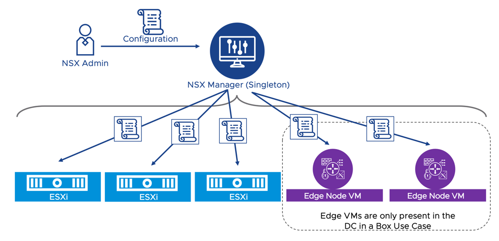
Figure 1: NSX Manager - Single point of management for network and security
2.2.2 ESXi Host
The ESXi hosts provide virtual machine connectivity via the VDS and constitutes the enforcement point for security policies. Each ESXi connects to the NSX manager appliance and receives the firewall configuration from the NSX Manager. The host pushes the firewall rules to the data plane filters, instantiated in the kernel, for each VMs’ virtual NIC (vNIC).
The NSX admin configures the scope of enforcement in the “Apply-To” field of a policy or rule. The host uses that information to ensure only relevant DFW rules are programmed on each virtual NIC. The hosts report back to the NSX manager the firewall policy realization status and statistics so that they are centrally located for easy consumption by the NSX admin via the UI or the API.
An independent instance of the distributed firewall is created for each VM vNIC. Each instance can be configured with unique firewall rules that are appropriate for the protected workload while NSX Manager provides the central management capabilities necessary in such a distributed security deployment. The NSX admin can configure each instance with unique firewall rules appropriate for the protected workload without the need for an agent.
Advanced security features such as Intrusion Prevention and Application Firewall are also available via the Intrusion Detection and Prevention System engine (IDPS) and the Deep Packet Inspection (DPI) engine respectively. Those components run in the ESXi host. The NSX Distributed Firewall module can pass traffic to the IDPS engine or the Deep Packet Inspection engine when the NSX admin specifies in the configuration that those services should be applied to a specific traffic flow.
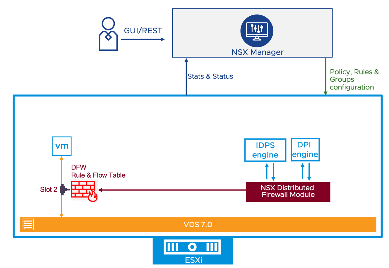
Figure 2: ESXi Host Distributed Security Data Plane Implementation
Only in the DC in a Box use case, the VDS provides advanced network services. When the NSX admin creates a new overlay segment, the virtual switches on the different hosts will create a virtual network on top of the existing basic connectivity provided by the physical network. The virtual machines on different hosts but the same network will communicate because the hosts will establish Layer 2 over Layer 3 tunnels via dedicated VMKernel interfaces named Tunnel EndPoints (TEPs). This mechanism allows the DC in a Box Administrator to create and delete new networks without coordinating with the physical network administrator.
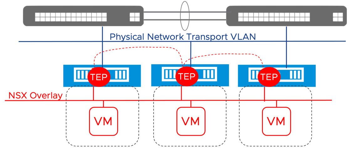
Figure 3: NSX Overlays
2.2.3 Edge Node VMs – Data Center in a Box Use Case Only
In the simple security for applications use case, the only additional virtual machine deployed on the collapsed vSphere cluster is the NSX Manager virtual appliance. We will deploy two other virtual appliances for the DC in a Box use case, the NSX Edge node VMs. These two VMs provide a pool of capacity for edge networking and security services such as routing with the physical network, Network Address Translation (NAT),Next Generation Firewall, DHCP server, DNS forwarder, VPN, and bridging. In the DC in a Box use case, all services are deployed as Active/Standby; two Edge Node VMs are required to provide high availability.
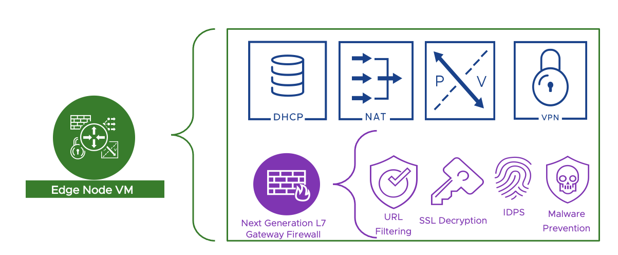
Figure 4: The edge Node VM provides edge networking and security services to the DC in a box solution
A gateway is an NSX configuration object that is deployed when the administrator desires to provide routing services via NSX. When only East-West routing within the data center is required, NSX instantiates the gateway on the ESXi hosts only. In this case, routing capabilities are fully distributed, and traffic never traverses the edge node VMs. Each host runs a distributed router component (DR) capable of locally routing the traffic for all the connected overlay segments and acting as the default gateway for the VMs on the host.
When peering to the physical network or network services are required, the NSX Manager instantiates the gateway on the edge nodes to apply more advanced functionalities to the traffic. Edge nodes participate in the NSX overlay network with the ESXi hosts. They received the traffic over those tunnels before processing it with L4-L7 capabilities and forwarding it to the physical network.
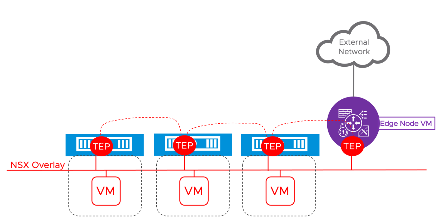
Figure 5: The edge node VM participates in the overlay while providing physical to virtual connectivity and network services
The DC in a Box design includes a single gateway deployed in Active/Standby across the two edge nodes, with all the edge networking stateful services part of the solution attached to it. The edge nodes do not follow the Active/Standby model because it’s the services running on top of them that can be active or standby, edge nodes are always active. Edge nodes could run a mix of active and standby services simultaneously. Still, because of the single gateway design in the DC in a Box use case, one of the edge nodes will run all the active services while the other will host all the standby services. This design resembles a physical network appliance model, where the traffic flow is predictable as one of the devices is not processing traffic until a failure occurs.
2.2.4 NSX Application Platform (NAPP) – Optional for both use cases
As of NSX Data Center 3.2, VMware has introduced the NSX Application Platform (NAPP). This is a new microservices based solution that provides a highly available, resilient, scale out architecture to deliver a set of core platform services which runs several new NSX features such as:
- NSX Intelligence (Application topology discovery and visualization, security policy recommendation)
- NSX Malware Prevention
- Network Traffic Analysis
- NSX Network Detection and Response
Even the most basic deployment of the simple security for application use case can benefit by the addition of NAPP thanks to the application topology mapping and security policy recommendation capabilities provided by NSX Intelligence. NAPP is required to activate some of the advanced threat prevention capabilities such as network traffic analysis (NTA), distributed malware prevention, and network detection and response (NDR). NAPP is not required for distributed intrusion prevention and detection (IDPS).
Deploying NAPP requires a Kubernetes cluster which meets the platform requirements. VMware Tanzu Kubernetes Clusters (TKC) and upstream Kubernetes clusters are the supported Kubernetes distributions. At minimum a cluster comprising a single control plane node and three worker nodes is required for a production deployment. System requirements for the different form factors are documented here.
In this guide, to facilitate the deployment of the NSX Application Platform and the supporting Kubernetes cluster, we recommend the use of the NAPP Automation Appliance. The NAPP Automation appliance automates the enablement of a vSphere with Tanzu workload domain on the target vSphere environment, the deployment of a TKC with appropriate specifications to support the NSX Application Platform, and the deployment of NAPP itself. The resulting architecture provides an end-to-end solution that is fully supported by VMware.
The vSphere with Tanzu deployment automated via the NAPP automation appliance will leverage VDS networking and it is the recommended approach for both the Simple Security for Application and the Data Center in a Box use cases. A total of eight additional virtual machine will be deployed on the target environments. Those VMs will include the Tanzu supervisor cluster (3 VMs), a HA-Proxy load balancer VM, and the guest cluster hosting the NSX Application Platform (4 VMs).
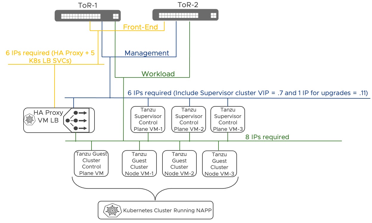
Figure 6: NAPP deployment leveraging Tanzu on vSphere with VDS Networking – Automated via the NAPP Automation Appliance
2.2.5 NSX Advanced Load Balancer (AVI) – Optional – Data Center in Box Use Case only
The NSX Advanced Load Balancer is built on software-defined principles. The architecture separates the data and control planes to deliver application services such as load balancing, application analytics, predictive autoscaling, and self-service for app owners. The platform provides a centrally managed, dynamic pool of load-balancing resources to deliver granular services close to the individual applications. This allows network services to scale near infinitely without the added complexity of managing hundreds of disparate appliances.
The NSX Advance Load Balancer deployment for the DC in a Box use case incorporates two components: the Service Engines and the Controller.
Service Engine (SE)
Service Engines handle all data plane operations and execute instructions from the Controller. The SE performs load balancing and controls all client and server-facing network interactions. It collects real-time application telemetry from application traffic flows and provides that information to the Controller. In the DC in a Box design, we provide high availability by deploying two SEs. Additional SE can be added, manually or dynamically via autoscaling, if the scale or the traffic requirements require it.
Controller
The Controller is the single point of management and control that serves as the “brain” of the system. As its name implies, the Controller implements the control plane. Controllers continually exchange information securely with the SEs. The health of servers, client connection statistics, and client-request logs collected by the SEs are regularly offloaded to the Controllers, which process the logs and aggregate analytics. The Controllers also send commands down to the SEs, such as configuration changes. Controllers and SEs communicate over their management IP addresses.
The controller hosts the NSX advanced load balancer console, a modern web-based user interface to manage and monitor applications. All services provided by the platform are available as REST API calls to enable IT automation, developer self-service, and a variety of third-party integrations.
The general recommendation is to deploy a cluster of three NSX Advanced Load Balancer controllers for high availability. Still, the DC in a Box solution adopts a singleton deployment model instead to minimize resource consumption in a small deployment. vSphere HA and backup restore procedure are used to recover the single Controller in case of a failure. The singleton deployment model can be scaled out to a clustered deployment of three NSX Managers if deemed necessary.
More information about the NSX Advanced Load Balancer Architecture can be found here.
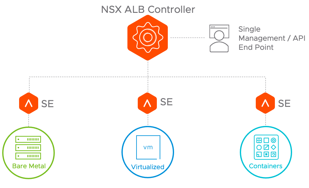
Figure 7: NSX Advanced Load Balancer Architecture
2.3 Simple Security for Applications Overview
2.3.1 Definition of Simple Security for Applications
Applications today are responsible for almost every company’s entire revenue stream and their ability to evolve and react to market demands. As a company tries to optimize its operations, expand into a new market, or enable a shift in the way they do business, these changes are accompanied by new application deployments or potentially significant application updates. As the reliance on these applications grows, the impact increases if they are compromised or fail.
A security solution that can keep pace is needed to increase the speed at which an organization can introduce or modify applications while still protecting them. A software-defined security solution is the best way to do this. VMware NSX is the ideal solution to address simple and complex security needs with the simple security for applications use case.
In the simple security for applications use case, the primary objective is to provide a robust security solution for one or more applications based on the tried-and-true zone-based security principles still prevalent in corporate IT environments. While this use case applies to environments of any size or type, this solution is focused on an environment that fits into the following classification:
- Brownfield: applications are already running on the existing infrastructure.
- Flexible footprint - two (2) to fifty (50) hosts deployment
- < 1000 Virtual Machines and most likely < 500 Virtual Machines
- Existing single vCenter, single cluster environment running vSphere 6.7 or later and VDS 6.6 or later
- Primary Routing and Switching is owned by the Physical Network and not the Software Defined Networking solution
The simple security for application solution requires the following NSX components:
- A single NSX Manager appliance running NSX version 3.2.1 or later
- ESXi hosts NSX installation orchestrated by NSX Manager
Optional additional component is the NSX Application platform (NAPP) deployed via the NAPP automation appliance. The NAPP deployment includes:
- 3 Tanzu supervisor cluster control plane VMs
- 4 Guest cluster Kubernetes nodes
- 1 HA-Proxy Load Balancer virtual machine
The simple security for application solution does NOT require the following NSX components:
- Edge node VMs
- Network overlay
The simple security for application solution is agnostic to the physical network topology, it can be deployed on any physical fabric type, and does not require any change or configuration of the physical equipment. Specifically, the simple security for applications does NOT require:
- Changing the MTU
- Create new VLANs (Unless the deployment incudes the NSX Application Platform (recommended), NAPP requires two new routable VLANs)
- IP routing reconfiguration
- Default gateway migration
As the environment grows up to the intended maximum of fifty hosts, the solution can absorb those changes without detrimental effect on the protected workloads. Above this scale, while the solution may not change, the resources required may.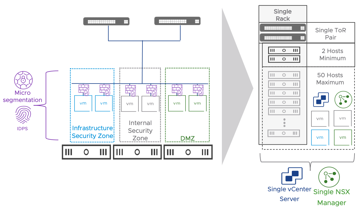
Figure 8: Simple Security Use Case Architecture and Features
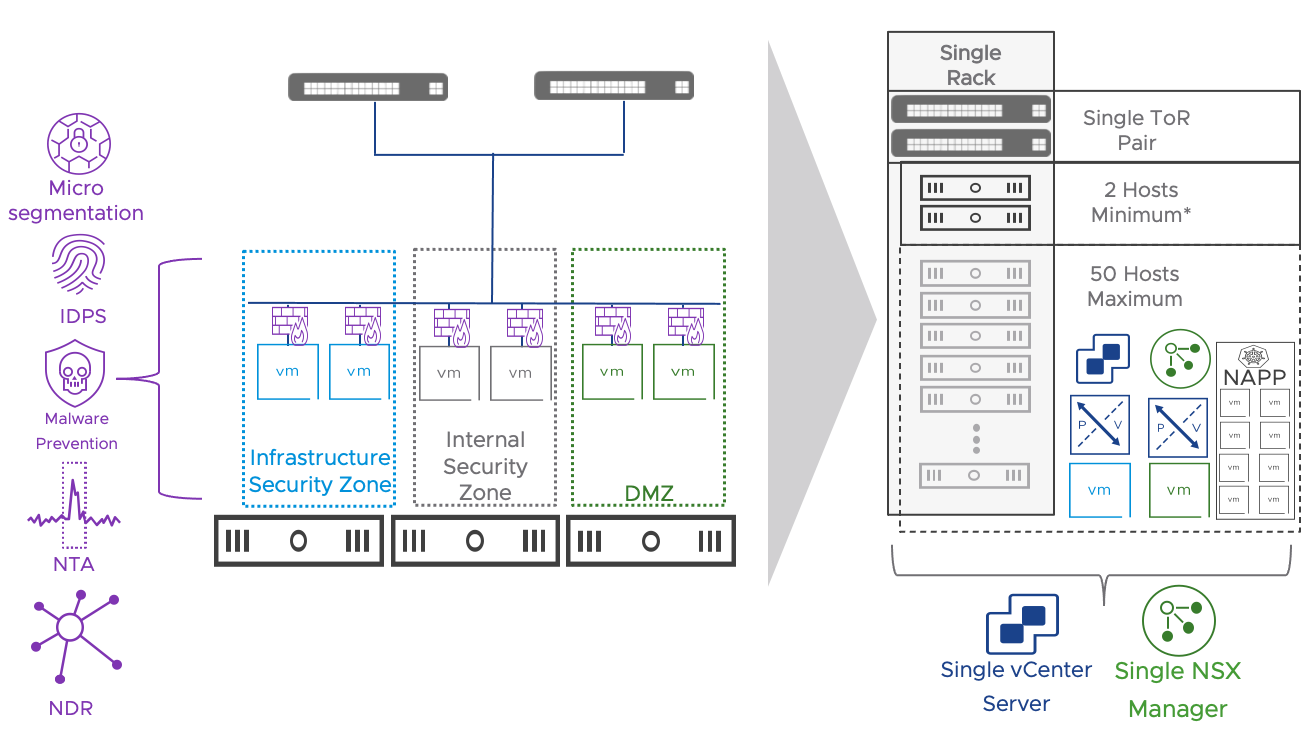
Figure 9: Simple Security Use Case Architecture and Features when the NSX Application Platform (NAPP) is deployed
2.3.2 Value to the Security Administrator
For an engineer with responsibility for security, incorporating a simplified Software-Defined Security solution is a game-changer. The engineer can now define security standards and apply them to the existing infrastructure regardless of the network topology implemented in the brownfield environment. In situations where the organization did not implement zone-based segmentation when building the virtualized infrastructure or when the security requirements changed over time, the security engineer can now provide the required segmentation without any dependency or coordination with the physical network.
In environments in the upper half of the range from a scale perspective (i.e., 25+ hosts), procuring hardware appliances with an adequate set of performance and functionalities can be costly. Purchasing decisions based on cost may hinder the environment's future growth. The NSX security model is fully distributed. Security functionalities are implemented leveraging unused CPU and memory resources on the workload compute infrastructure. Scaling the compute infrastructure will automatically scale the performance of the security services.
The other significant benefit is around audit and operations. By implementing this solution, the engineer can both test and validate rules through simplified and centralized logging. Rules can have unique custom identifiers, which can be seen in vRealize Log Insight or any other log analysis tool integrated through Syslog. They can troubleshoot their rules using the TraceFlow tool integrated into NSX Manager, and they can quickly implement emergency rules while seeing their effect on the application rules below.
If NAPP is included as part of the solution, the security administrator gains access to the NSX Intelligence analytics and visualization capabilities. Those functionalities greatly facilitate the adoption of NSX Distributed Firewall providing application topology discovery and visualization, and security policy recommendations.
2.3.3 Value to the Virtual Infrastructure Administrator
The Simple Security for Applications use case makes the Virtual Infrastructure Administrator’s (VI Admin) job more manageable. Security policies are applied to the individual VM and are retained regardless of where the VM is deployed or moved. The modification or installation of agents on virtual machines is unnecessary because all the security functionalities are implemented on the underlying hypervisor. Enabling those capabilities does not require rebooting or placing the hosts in maintenance mode.
The ability to use policies based on Tags and VM Properties enables the VM Admin to leverage automation tools to deploy new workloads, which will inherit a level of security without direct interaction with the security team. The same approach is feasible with a home-grown script, supported automation tools such as Ansible and Terraform, or end-to-end automation solutions such as vRealize Automation.
2.3.4 Role of NSX in the Simple Security Use Case
NSX provides robust security capabilities that the security engineer can implement with no changes to the existing network environment. This is not possible with a traditional security solution or a physical appliance as they must sit in line with the traffic.
Here are a few of the capabilities NSX provides in the context of the simplified security use case enabling a straightforward way of securing an environment:
- Comprehensive L4-L7 Distributed Firewalling capable of protecting workloads transparent to the Workload and the Physical Network
- A High-Level human-readable vernacular for defining and implementing Security rules/policies
- Integrated Audit and Troubleshooting tools for fine-tuning the security policies and rulesets
- Access to more advanced security capabilities such as IDS/IPS without the need to redeploy or rearchitect the Simplified Security Solution at any point in time when the organization identifies a need for those more advanced capabilities.
The distributed security functionalities part of the solution are summarized in the table below.
| Functionality | License | NAPP Required |
| L2 – L4 firewalling | Distributed Firewall | NO |
| L7 Application Identity based firewalling | Distributed Firewall | NO |
| User Identity based firewalling | Distributed Firewall | NO |
| NSX Intelligence (flow visualization, policy recommendation) | Distributed Firewall | YES |
| IDS/IPS (Signature and behavioral based) | Distributed Firewall + Threat Prevention | NO |
| Network Traffic Analysis | Distributed Firewall + Advanced Threat Prevention | YES |
| Network Malware Prevention | Distributed Firewall + Advanced Threat Prevention | YES |
| Network Detection & Response | Distributed Firewall + Advanced Threat Prevention | YES |
Table 1: Security Features part of the Simple Security for Applications Use Case
2.3.5 Extending the Simple Security Use Case
2.3.5.1 Multiple vSphere Clusters
Extending the simple security to a multi-cluster vSphere environment is completely transparent and does not require any additional design consideration. If the appropriate vSphere and VDS versions are available (6.7+ and 6.6+ respectively) the simple security for application use case can be implemented following the same approach described for a single collapsed cluster environment. A single or multiple VDSs are supported within the same vCenter server deployment.
2.3.5.2 Multiple vCenter servers
The simple security for application use cases can be extended to environments encompassing multiple vCenter servers. NSX Manager provides a single configuration and operational point of management across the different compute managers. In this case the only limitation to consider is that we cannot leverage the vSphere plug-in for NSX. The management of the security policies needs to be performed accessing the NSX GUI directly and cannot be embedded into the vSphere client for a unified experience.
2.4 Datacenter in a Box Overview
2.4.1 Definition of the Datacenter in a Box
We designed the Data Center in a Box solution to create an easily deployable self-contained environment with as few outside dependencies as possible while providing a full-featured environment. This solution draws a hard line between the physical infrastructure and potentially hosting provider environment and the Customer Controlled software-defined environment created by vSphere and NSX. This solution is focused on an environment with the following characteristics:
- Greenfield: brand new installation.
- Relatively small, two (2) to fifty (50) host deployment
- < 1000 Virtual Machines and most likely < 500 Virtual Machines
- Single vCenter, single cluster environment running vSphere 7.0 and VDS 7.0
- Primary Routing and Switching is owned by the Software Defined Networking solution
In its most basic implementation, the DC in Box architecture includes a pair NSX Edge VMs providing networking and security services. Workloads are placed on overlay networks that can be provisioned transparently to the physical network configuration. The entire virtual topology is hidden behind a NAT boundary minimizing external network dependencies. Distributed security services are available to the virtual machines located on overlays and can be supplemented by those provided by the NSX Next Generation Gateway Firewall running on the NSX Edges.

Figure 10: Datacenter in a Box Use Case Architecture and Features
When the NSX Application Platform is deployed, additional capabilities are unlocked. They include:
- NSX Intelligence (Application topology discovery and visualization, security policy recommendation)
- NSX Malware Prevention
- Network Traffic Analysis
- NSX Network Detection and Response
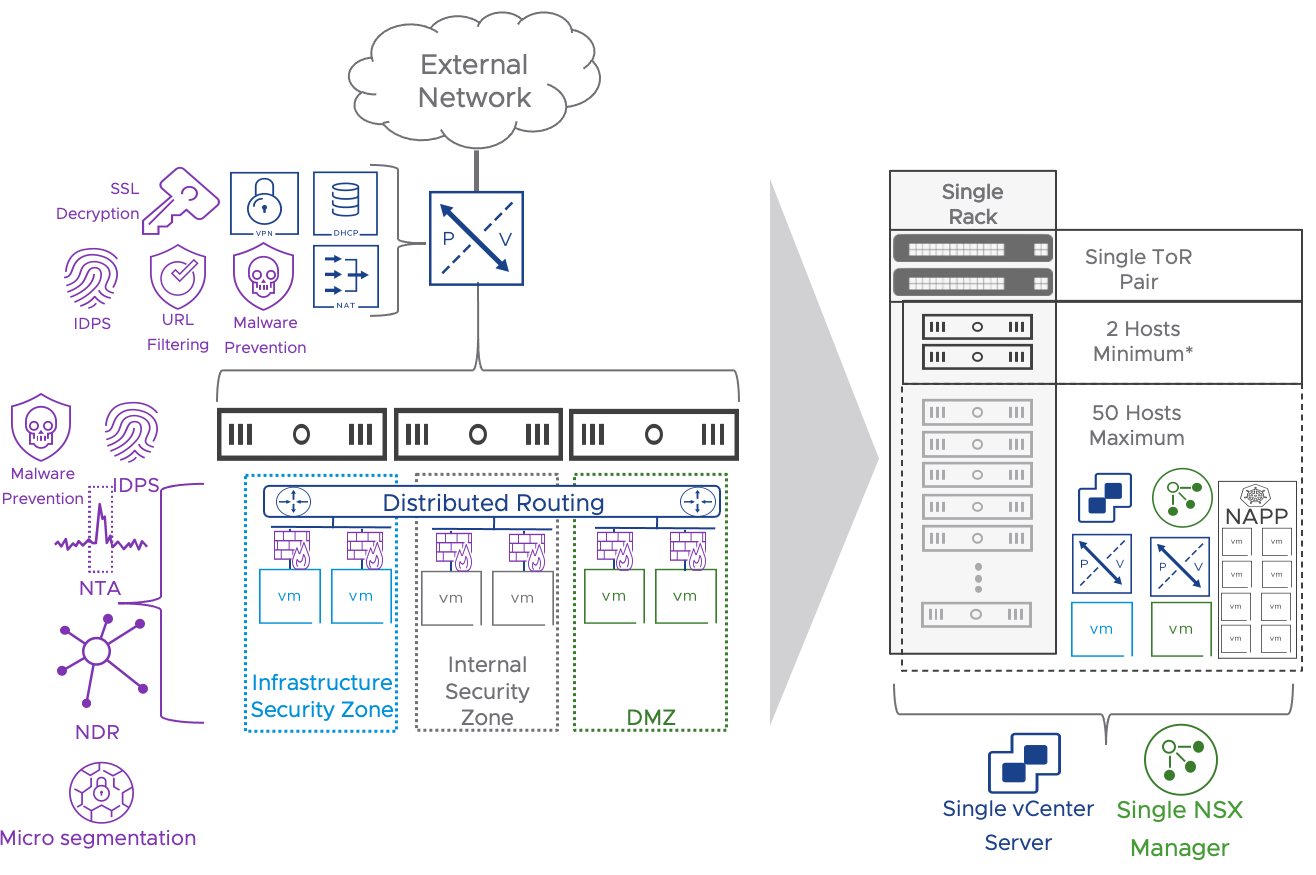
Figure 11: Datacenter in a Box Use Case Architecture and Features when adding NAPP
When the deployment requires load balancing services, the NSX advanced Load Balancer is deployed and integrated with NSX based on the model described here. A single NSX ALB controller and a pair of SEs are added to the design.
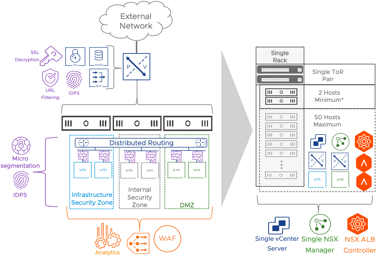
Figure 12: Datacenter in a Box Use Case Architecture and Features when adding NSX Advanced Load Balancer
The networking and security functionalities part of the solution are summarized in the table below. All the Distributed Security services available for the Simple Security for applications use case are optionally available for the DC in a Box use case. They are not repeated here.
| Functionality | Availability | Notes |
| Network Virtualization | Out-of-the-box | Layer 2 and layer 3 network virtualization is provided by the NSX Gateway and Geneve overlay networks. |
| L4 Gateway Firewall | Out-of-the-box | The NSX Gateway provides edge security functionalities and protects the DC in the Box from the external network. |
| Network Address Translation (NAT) | Out-of-the-box | The NSX Gateway hides the internal IP schema of the DC in a box. This approach minimizes physical network dependencies. |
| L4 Zone Based Segmentation | Out-of-the-box | Two security zones are implemented via distributed firewall: DMZ and Internal. |
| Site to Site VPNs (Optional) | Post Deployment - Manual Implementation | L2 and L3 VPNs can be implemented on the NSX Gateway. |
| L4 Application Micro-segmentation (Optional) | Post Deployment - Manual Implementation | The administrator can implement a zero-trust security approach for critical applications leveraging NSX Distributed Firewall. |
| L7 Distributed Next Generation Firewall (Optional) | Post Deployment - Manual Implementation | The administrator can add AppID, FQDN and Identity Based firewall functionalities via the NSX Distributed Firewall. |
| Distributed IDS/IPS (Optional) | Post Deployment - Manual Implementation | Distributed IDS/IPS are available to any workload without any redesign. |
| L7 Next Generation Gateway Firewall (Optional) | Post Deployment - Manual Implementation | The administrator can add AppID, FQDN and Identity Based firewall functionalities via the NSX Gateway Firewall. |
| NSX Gateway URL Filtering (Optional) | Post Deployment - Manual Implementation | The administrator can create access rules based on predefined URL categories and reputation levels. Custom URLs are supported. TLS decryption is required to enforce URL filtering on TLS traffic. |
| NSX Gateway Network Sandboxing - Malware prevention (Optional) | Post Deployment - Manual Implementation | NAPP is required. TLS decryption is required to provide the service to encrypted traffic. |
| NSX Gateway IDS/IPS (Optional) | Post Deployment - Manual Implementation | IDS/IPS rules can be configured on the NSX Gateway. Combined with TLS decryption it provides protection for encrypted traffic (Not available for the distributed IDS/IPS) |
| NSX Gateway TLS Decryption | Post Deployment - Manual Implementation | Extend advanced security features to encrypted traffic. |
| Load Balancing + WAF + Analytics (Optional) | Post Deployment - Manual Implementation | The administrator can add Load Balancing capabilities by implementing the native NSX load balancer or by deploying the NSX Advanced Load Balancer (Preferred). Link to the NSX-T AVI Integration. |
Table 2: Features included in the DC in a Box Use Case
2.4.2 Datacenter in a Box Use Cases and Business Drivers
The following sub-sections cover the business drivers and the use cases of the DC in a Box solution.
2.4.2.1 Adopting Cloud Consumption Model with Data Center in a Box
With the advent of public cloud infrastructure services, internal IT customers have significantly more choices on how and where they want to consume the entire stack. This use case allows the internal IT organization to leverage software-defined networking, security, and services (NAT, FW, VPN, and LB) to create comparable self-contained environments. This design pattern aims to address a variety of formations such as small businesses or footprint, consolidation of fragmented environments, support and life cycle of various services (i.e., appliances for the services), and service providers who can provide hosted or managed services. Admins can use the small footprint solution proposed in this design for a separate or combined prod/QA/Test environment with a full stack of services. For example, QA or test environments may be self-contained from a compute perspective and deployed with overlapping IP addresses. NAT and DFW can isolate the different tenants when leveraging common compute resources.
A managed service provider may require quickly deploying a new independent environment for a new customer in their data center.
In some cases, the managed service provider is the IT organization itself. It may not have ready-for-consumption infrastructure to support ad hoc departmental initiatives. They need to rely on the quick deployment and consumption of ad-hoc resources.
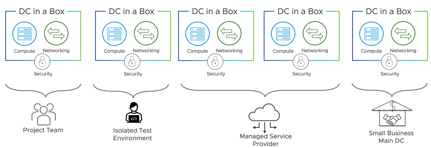
Figure 13: DC in a Box Independent Units of Compute
2.4.2.2 Appliance Sprawl
One of the challenges of operating an infrastructure based on independent pods of resources is the overhead imposed by the networking and security in rack space, power, and cooling. A traditional independent datacenter rack often has between 10 and 30 rack units dedicated to networking and security appliances. Those appliances may include top of rack switches, routers for Internet or WAN connectivity, and VPN-capable firewall appliances. In some cases, the security stack expands to a dedicated web gateway, intrusion prevention, load balancer, and web application firewall appliances. Dedicating many resources to networking and security in a small footprint solution is not economically viable or practical. VMware NSX allows virtualizing the entire Networking and Security functions eliminating the need to deploy physical appliances. The entire rack can be dedicated to generic servers capable of running application workloads and network and security services. The derived benefits drive the possibility of running independent units of computing efficiently and cost-effectively.
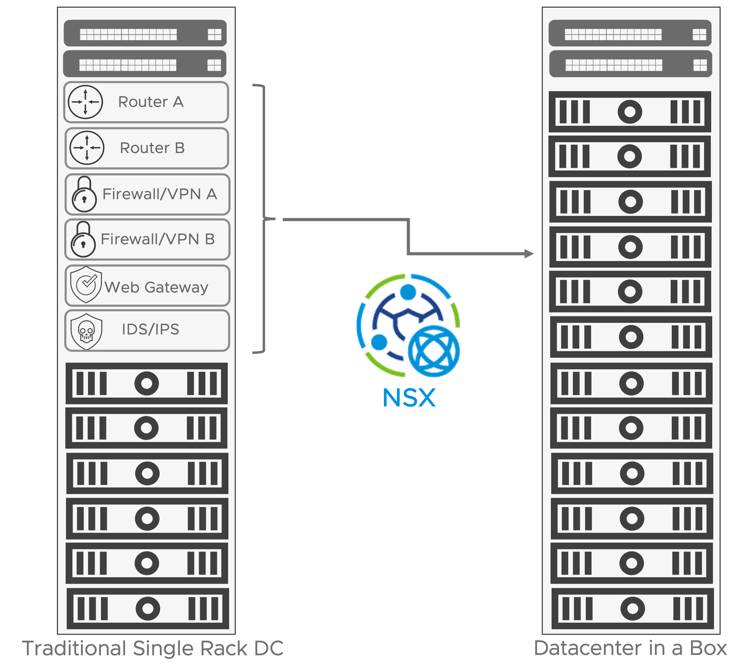
Figure 14: Appliance Sprawl vs DC In a Box
2.4.2.3 Vendor Sprawl
The networking and security stack in a data center is generally comprised of appliances from different vendors. While those appliances support standard protocols such as Ethernet and IP, and the administrator can integrate them via a coexistence model, every deployment is a snowflake that the IT organization is responsible for designing and validating. These problems are especially of concern when the organization must carefully assess high availability and performance requirements to meet the targeted Service Level Objective (SLO) and Service Level Agreement (SLA). Designing and assessing a full-stack networking and security solution may take quite a lot of time, resources, and expertise, delaying the organization's time to bring the solution into production.
Day two operations management represents a risk too. A heterogeneous solution may require the manual reconfiguration of multiple pieces of equipment or the creation and support of a custom-built automation tool. Troubleshooting and escalation may also become tedious and time-consuming as multiple parties are involved. The DC in a Box addresses this challenge by providing a single platform covering a small footprint data center's entire network and security needs.
2.4.2.4 IT Staff Expertise
Small and medium organizations may not have the in-house resources to design and validate heterogeneous networking and security solutions. In such situations consulting services from third-party system integrators are often required and increase the overall adoption cost for the solution. Day-to-day activities such as configuration changes, triage, and troubleshooting require staff with various skill sets trained on different vendors and products. Developing and maintaining such a team is costly and time-consuming and may be out of reach for some organizations. The Total Cost of Ownership (TCO) is essential in assessing an implemented solution's success. The Datacenter in a box solution alleviates this pain point by requiring expertise in a single vendor product: VMware NSX.
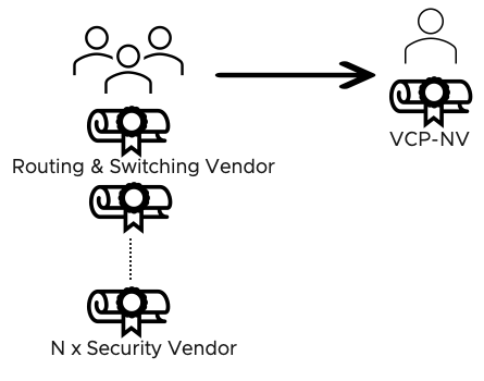
Figure 15: Vendor Sprawl and IT Staff Reduction for the DC in a Box
2.4.3 DC in a Box in a Brownfield Environment
The DC in a Box solution generally targets greenfield environments because enterprise architects can use it as an atomic building block to create a more complex infrastructure platform. In some situations, the organization may be looking to deploy the DC in a Box solution in a brownfield environment where workloads are already running. This approach is possible without modifying the DC in a Box design or its pre-requisites. If the environment can satisfy all the assumptions outlined in the solution design section, the DC in a Box can be implemented side by side to the existing workloads. Existing VMs will keep using networking and security services offered by the physical network, new workloads deployed on the new virtualized topology those provided by VMware NSX instead. See diagram below.
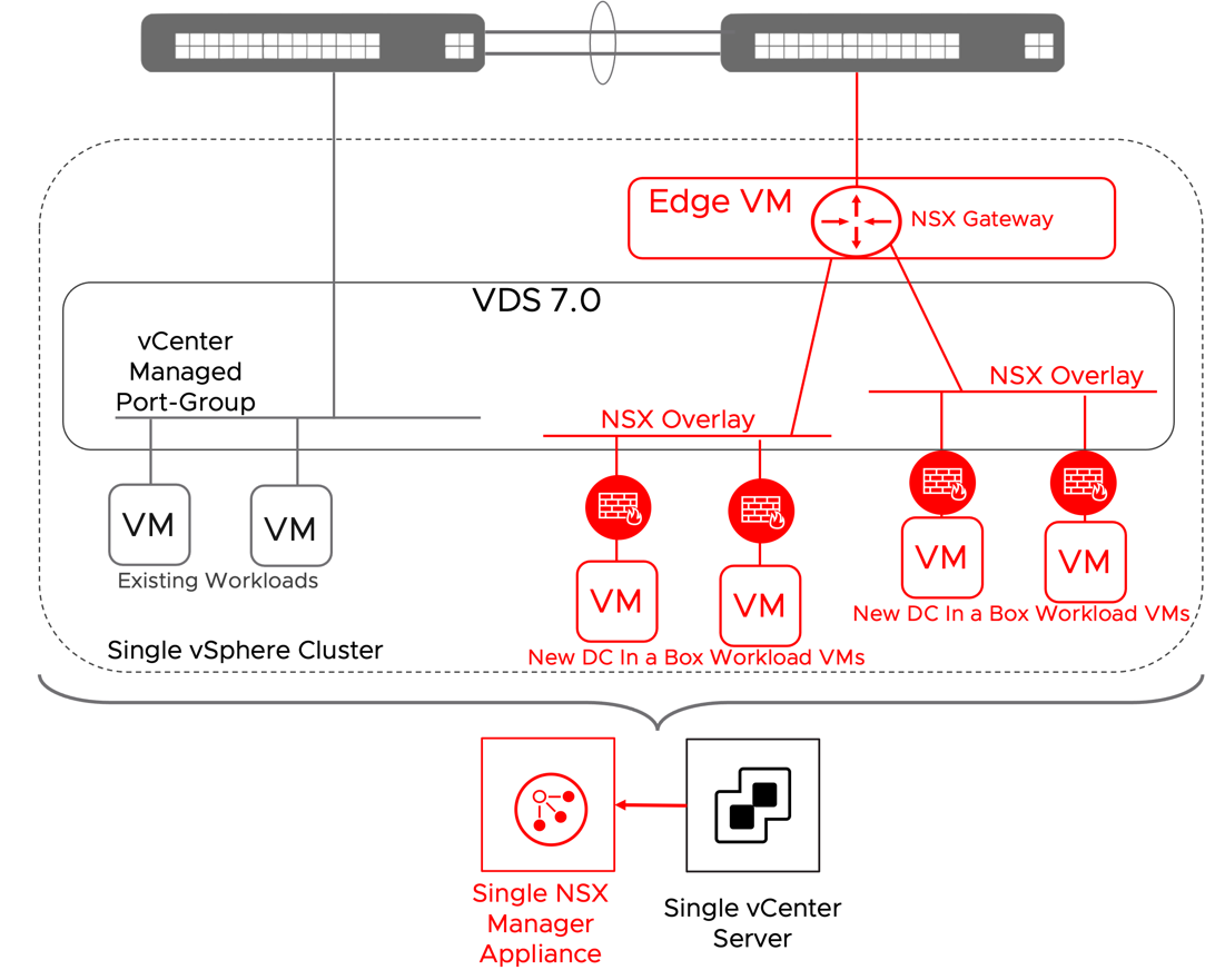
Figure 16: DC in a Box Deployed in a Brownfield
When the primary concern is integrating the existing workloads into the DC in a box networking model, the more straightforward approach is to leverage a service interface on the NSX Gateway. The NSX Gateway will become the default gateway for the existing workloads. While adopting the simple security for applications use case for the exiting workloads is entirely transparent to the physical network, moving the networking services to the NSX gateway is not. A security-only integration is recommended unless specific business drivers call for the networking integration. One example could be providing security services for bare metal servers. The networking integration via the service interface is outlined in the diagram below.
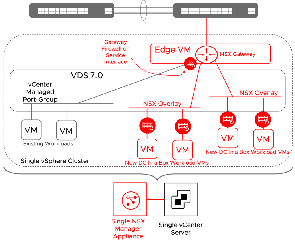
Figure 17: DC in a Box in a Brownfield + Networking Integration
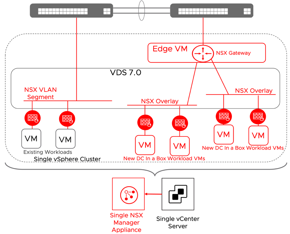
Figure 18: DC in a Box in a Brownfield + Security Integration
Additional integration strategies are possible but not covered in this document because of their operational complexity. Those presented represent what we deem the most effective at delivering business value while striving for simplicity.
3 Solutions Design
3.1 Overview of recent relevant NSX enhancements
The solutions presented in this document have been validated for NSX version 3.2.1, but they should work with any later release. They benefit from the recent introduction in the NSX platform of some critical functionalities. We will review them here because of their relevance in the presented designs and because the reader may not be familiar with them already. Those functionalities are:
- NSX Distributed Security on distributed virtual port-groups
- NSX Deployment on VDS
- Single TEP network shared between Edge and Host Transport Nodes in a collapsed cluster
- Singleton NSX manager support
3.1.1 NSX Distributed Security on distributed virtual port-groups
Starting with NSX 3.2, it is possible to protect workloads connected to vSphere distributed port-groups via all the native NSX distributed security services (DFW, IDPS, NTA, Malware Protection, NDR). In deployments that do not include overlays such as the simple security for application use case, there is no need to migrate the VMs to NSX VLAN segments. This capability allows to transparently insert in brownfield environments the NSX Distributed Firewall and the other NSX distributed security services. The Virtual Infrastructure Administrator retains control of the virtual infrastructure management through vCenter, including the management of the VDS and port-groups. The security administrator can manage and apply policies via NSX manager for a complete roles and tools separation. Key requirements and implementation considerations for the solution are:
- No need to create NSX Segments in the NSX UI:
- dvpgs are discovered by NSX, and segment profiles can be applied to them in the NSX UI (IP Discovery, Spoof guard, switch security, etc.)
- DFW is enforced on all VMs connected to dvpgs
- NSX networking features based on overlay are NOT available
- Requires vSphere 6.7+, VDS 6.6+, NSX 3.2+
- No DFW for infrastructure traffic
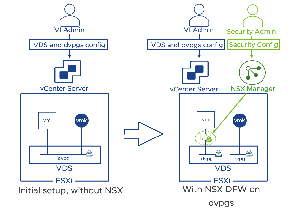
Figure 19: Distributed Firewall on vSphere Distributed port-groups
In organizations where the separation of roles between the VI Admin and the Security admin is not desirable, and the VI Admin takes ownership for the implementation of NSX Security policies, it is possible to manage the NSX security configuration via the vSphere client thanks to the vSphere plug-in for NSX. The vSphere plug-in for NSX provides single sign on (SSO) between vCenter and NSX and require vCenter 7.0U3 or later. Key requirements and implementation considerations for the vSphere plug-in for NSX are:
- vSphere plug-in for NSX installation can only happen at the NSX Manager deployment time. If NSX Manager is already deployed, the vSphere plug-in for NSX cannot be installed.
- A single NSX Manager is supported, a 3 nodes NSX Manager cluster is not supported (NSX Manager cluster is supported starting with NSX 4.0.1)
- When leveraging the vSphere plug-in for NSX, NSX Manager can only manage a single vCenter. The ability to manage multiple compute managers is not available.
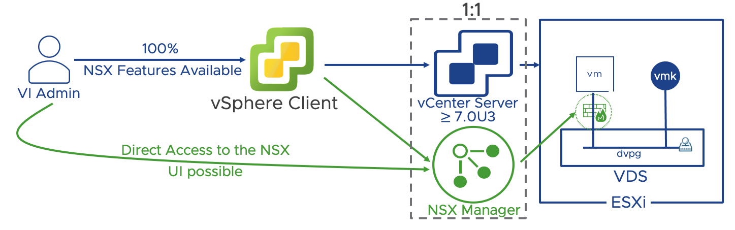
Figure 20: vSphere plug-in for NSX
When NSX security of vSphere distributed port-groups is enabled on a vSphere cluster (via the security only preparation), overlay networks are not available. Overlay networks are available in cluster prepared for network and security. Security only and Network & Security prepared clusters can coexist within the same NSX and vCenter installation.
Key implementation considerations for Network & Security clusters compared to security only clusters are:
- Distributed security is available on VLAN networks, but VMs must be connected to NSX VLAN segments
- VMs connected on dvpg are excluded from NSX distributed firewall and any other distributed security feature
- Converting a cluster between the two modes requires removing NSX from the cluster and install it again
In the simple security for application use case, the vSphere cluster is prepared for security only, in the DC in a Box use case for networking and security.
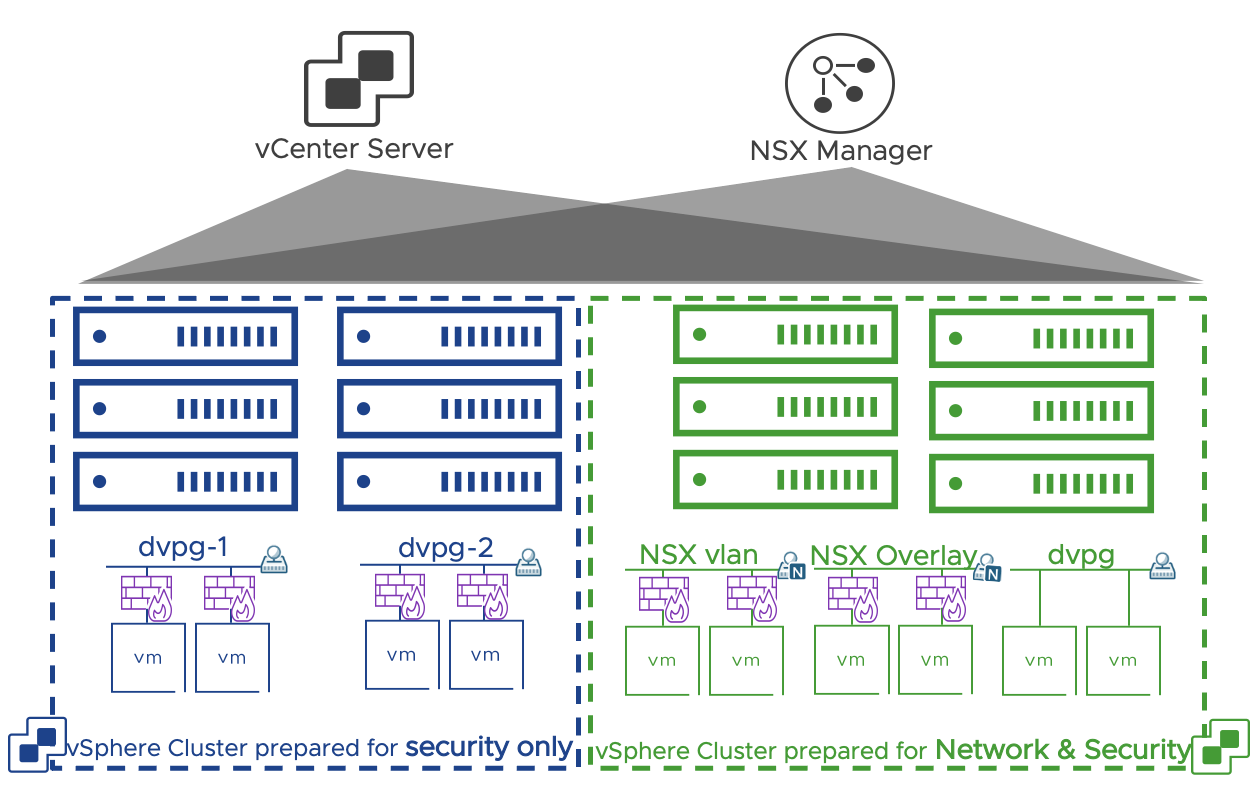
Figure 21: Security only vs Networking and Security clusters
3.1.2 NSX on VDS (Networking and Security Clusters)
3.1.2.1 Overview
Starting in NSX 3.0 and vSphere 7, we can run NSX on top of an existing VDS. The change only affects vSphere. When running NSX on VDS, all the NSX functionalities are preserved including distributed security and overlays, but the NSX segments are also presented as port groups on the VDS. This model allows traditional dvpgs and NSX segments to share the same virtual switch and uplinks, while in the past, deploying NSX required different virtual switches and uplinks. We can now select the workloads requiring NSX services and place them on NSX managed port-groups while leaving on traditional dvpg the components that we want to exclude from the NSX purview.
For in-depth coverage of the NSX on VDS model, please review this TechZone article. The following sections will address how the two use cases covered in this document specifically benefit from it.
3.1.2.2 DC in a Box
Collapsed cluster design defines a deployment model where all the components of the stack (Management and Edge) along with workloads share the same cluster. VDS 7.0 can have some of its port-groups managed by vCenter and some by NSX Manager. Placing NSX Manager on a dvpg managed by vCenter eliminates any circular dependency and makes implementing a collapsed cluster design straightforward.
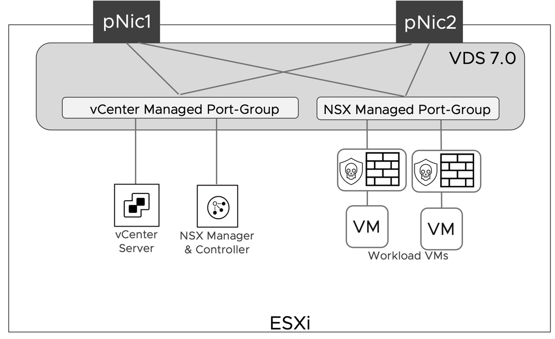
Figure 22: Management Components network placement on VDS
3.1.3 Single TEP Network (DC in a box)
Edge node VMs are deployed on an NSX prepared host in a collapsed cluster design. This is required so that the same server can host both the edge node and the workload VMs. When deploying an edge node on an NSX prepared host with only two uplinks in versions earlier than 3.1, it was required for host and edge TEP interfaces to be on different subnets and VLANs. The reason being the ESXi host was able to process Geneve encapsulated packets only when they were received on a physical uplink.
In NSX version 3.1, VMware eliminated this limitation, and now we support inter-TEP traffic within a host. This improvement does not impact the simple security use case because overlay traffic is not part of the design but positively impacts the DC in a Box solution by simplifying the requirements on the physical network.
Confining the entire overlay traffic to a single VLAN reduces the physical network requirements. The network administrator now has a single VLAN rather than two to configure and enable jumbo frames. Also, a single VLAN model does not require routing overlay traffic, so no switched virtual interfaces (SVIs) and first-hop redundancy protocol to be enabled either. In the past, it was common for the network administrator to enable L2 jumbo frames on the physical switches but forget to do the same for Layer 3 traffic under the SVIs configuration. Reducing the configuration points on the physical network reduces the risk for error and a frustrating adoption experience.
In the context of a simplified design, using a single overlay transport VLAN is also advantageous from a security perspective. When we must route overlay traffic, the SVIs on the transport network can serve as an entry point to the overlay network because overlay protocols such as VXLAN and Geneve do not provide embedded security. There is no better way to secure the transport network than completely isolating it on a single layer 2 domain that only the participating transport nodes can access. Securing a routed transport network requires the use of additional physical network functionalities such as an external firewall, ACLs, or VRFs, which are not in line with the goals of a simplified design.
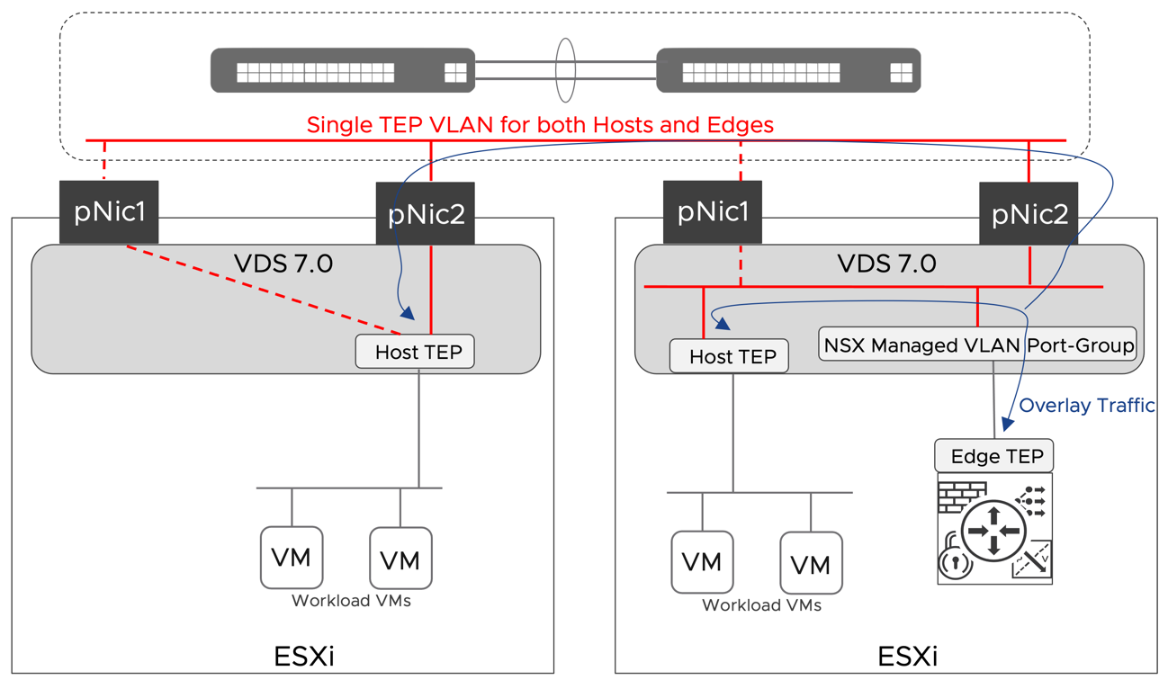
Figure 23: Inter TEP Communication within the same host
3.1.4 Singleton NSX Manager
The resources required to run a cluster of three NSX Managers may represent a challenge in small environments. In NSX version 3.1, VMware supports deploying a single NSX manager in production environments. This minimal deployment model relies on vSphere HA and the backup and restore procedure to maintain an adequate level of high availability.
vSphere HA will protect against the failure of the physical host where the NSX manager is running. vSphere HA will restart NSX Manager on a different available host. Enough resources must be available on the surviving hosts; vSphere HA admission control can help ensure they are available in case of failure.
Backup and restore procedures help in case of failure of the NSX manager itself. The SFTP server where the backup is stored should not be placed on an infrastructure shared by the DC in a box.
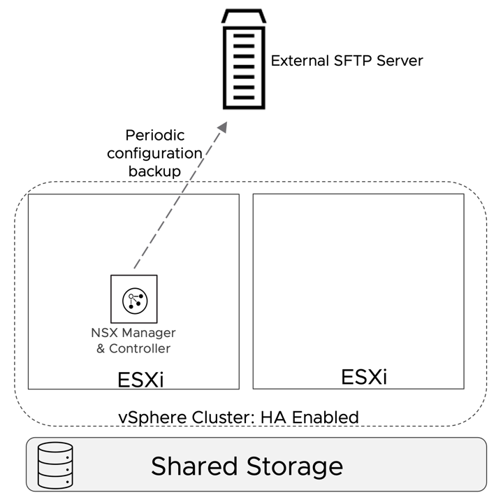
Figure 24: Singleton NSX Manager HA Model
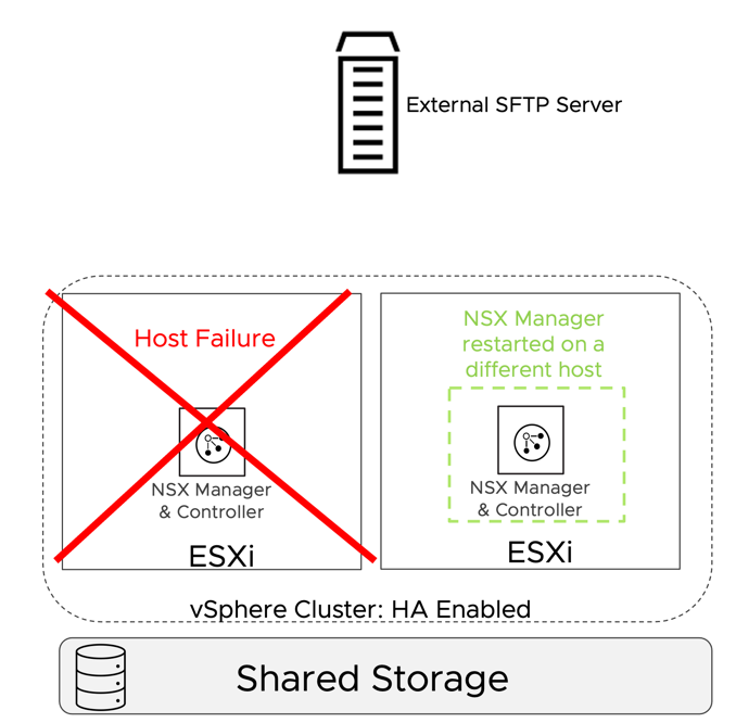
Figure 25: Singleton NSX Manager - Failure of the ESXi host
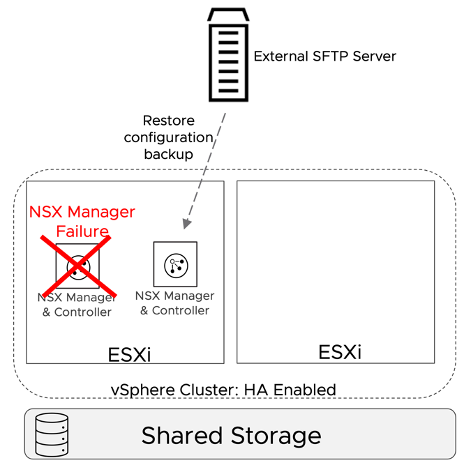
Figure 26: Singleton NSX Manager - Failure of the NSX Manager
3.2 Design terminology
The detailed design for the Simple Security for Application and Data Center in a Box use case presented in the next sections will use a set of assumptions and design decisions. In the context of this document, those terms are defined as follows.
Assumption: a required environment property before the use case is implemented. Assumptions define the scope of supportability for the solutions. All assumptions for the selected use case must be met before implementing it. Assumptions cover the physical network, compute hardware specifications, virtual infrastructure design, and authentication solutions.
Design Decision: an arbitrary choice about how the software-defined networking and security solution is implemented. The solution goals drive design decisions.
Each assumption or design decision is associated with an identifier for easy reference. The identifier has three parts (i.e., SS.AS.1 or DC.DD.1). The first two letters identify the use case, SS for Simple Security, DC for Datacenter in a Box. The third and fourth letters distinguish assumptions (AS) from design decisions (DD). The digits at the end represent numerical identifiers.
3.3 Simple Security Solution Design
3.3.1 Assumptions
The solutions in this document make a set of assumptions about the virtual infrastructure and supporting services. We made these assumptions to simplify the deployment and enable a quick path to consumption of the use cases addressed by the solutions. Before modifying one of these configurations or assumptions that are described, it is recommended that an evaluation is performed to determine if the benefit of modifying the solution outweighs the additional effort that it may require.
We do not provide any recommendation or assumption regarding the physical network, because the simple security solution is completely agnostic to it.
3.3.1.1 Virtual Environment Assumptions
The solutions in this document all assume a vSphere 6.7 or later based environment inside a single vSphere Cluster used in a homogenous manner to present hosting, network, and security services to the workloads that run on top of it. This type of environment from an NSX perspective is called a Fully Collapsed Cluster design. This is because Management Workloads and Production Workloads running on the environment are hosted on a single cluster. We made the following assumptions for the virtual environment to enable this design.
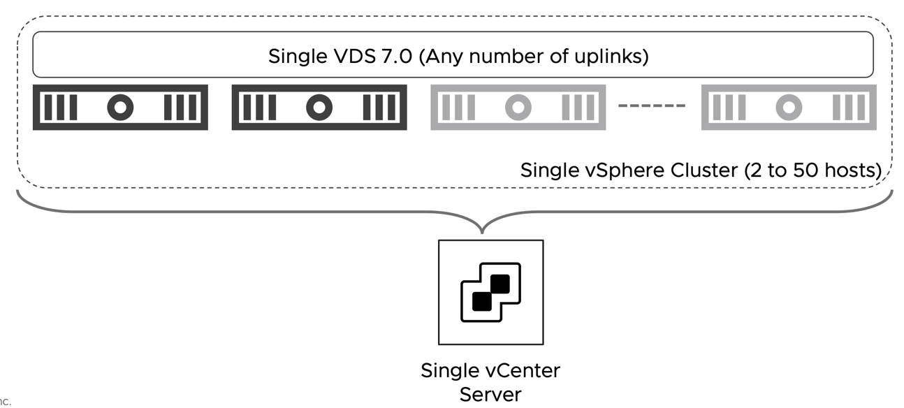
Figure 27: Simple Security - Virtual Infrastructure Assumptions
| # | Assumption | Description | Justification |
| SS.AS.1 | The vSphere environment is running version 6.7 or later | The vCenter server and the ESXi hosts are running on the software version 6.7 or later | vSphere 6.7 is required to dramatically simplify the implementation of NSX distributed security services for VMs connected to vSphere dvpgs. |
| SS.AS.2 | vCenter Server appliance deployment size at least small. | The small size vCenter appliance can support up to 100 hypervisors and 1000 VMs. | The small size can support up to upper boundary of the solution in scope. |
| SS.AS.3 | vCenter Server is deployed on the Management Network VLAN and connected to a vCenter managed dvpg. | vCenter server connectivity is provided by the physical network and completely independent from NSX. | Provides direct secure connection to the ESXi hosts and NSX Manager. |
| SS.AS.4 | Collapsed Cluster Design | Single vSphere collapsed cluster where Management appliances, and Workloads all reside on the same cluster. | Maximizes available resource utilization. |
| SS.AS.5 | VDS 6.6 or later spanning the entire cluster. | The VDS version must be 6.6 or later to support NSX security distributed services on dvpgs. | A single or multiple VDS are supported as long as they are version 6.6 or later. |
| SS.AS.6 | vSphere HA is enabled | Use vSphere HA to protect all virtual machines against failure. | vSphere HA supports a robust level of protection for the NSX components availability. |
| SS.AS.7 | NTP server is available | vCenter and the ESXi hosts are synchronized to a reliable NTP server. | Firewall logs are generated by the ESXi servers. NTP synchronization ensures that the timestamps are accurate. |
Table 3: Virtual Environment Assumptions for Simple Security Solution
3.3.1.2 Assumptions Access and Authentication
A critical component for any environment meant to host production workloads is its ability to control, track, and provide access to those teams and systems that need to access the environment. NSX provides a granular role-based access control capability through integrations with enterprise grade authentication directories. One requirement is to configure the integration between NSX Manager and vCenter Server with a corporate directory that meets the organization’s requirements for security and compliance.
It is generally recommended to tie the built-in roles in NSX to groups in your corporate directory where they match responsibilities of existing teams for this environment.
For the simple security for application use case, we assume that no complex RBAC is required and that it is sufficient to entitle a group of users to manage the entire NSX solution. For such simple requirements the SSO capabilities between vCenter and NSX Manager provided by the vCenter plug-in for NSX are good fit. It is sufficient to entitle vCenter users (local or external) to the NSX Administrator role and they will automatically have access to manage NSX through the vSphere Client.
If the requirements for RBAC are more complex, or direct access to the NSX GUI is required bypassing the vSphere client, a direct integration between NSX and the Active Directory can be configured.
In this design NSX will leverage the SSO capabilities of the vSphere plug-in for NSX.
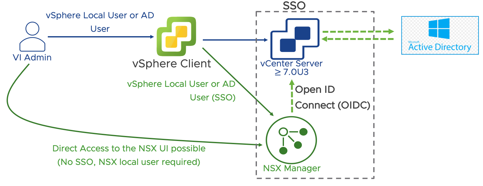
Figure 28: NSX Active Directory Authentication via the vSphere plug-in for NSX
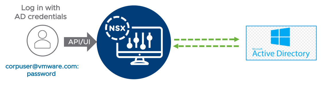
Figure 29: NSX Active Directory direct Integration
| # | Assumption | Description | Justification |
| SS.AS.8 | Microsoft Active Directory exists, and it is integrated with vCenter | NSX Manager is managed via the vSphere Client and benefits from the SS0 capabilities across vCenter and NSX. | MS Active Directory is the most common directory service in SMEs and it is commonly integrated with vCenter. No action is required on NSX to leverage Active directory authentication when NSX Manager is deployed via the vSphere plug-in for NSX. |
| SS.AS.9 | Granular RBAC is not required. It is sufficient to entitle a set of users to have full control of NSX. | The vSphere plug-in for NSX does not allow to map vSphere roles to all the NSX pre-defined roles or any custom role. A user with the “NSX Administrator” role in vCenter will be mapped to the Enterprise Admin role in NSX. | In SMEs a single individual or a small team often controls the entire NSX platform. If more granular RBAC is required, the direct integration of NSX with the organization Active Directory should be implemented. |
Table 4: Access and Authentication Assumptions for Simple Security Solution
3.3.2 NSX Design
3.3.2.1 Scale and Placement of Management and Data Plane Components
The Management Components in this solution are the vCenter Server Appliance, NSX Manager Appliance, and vRealize Log Insight. While native HA/Clustering solutions are available for them, we are leveraging vSphere High Availability for their availability profile in this design. While this design assumes that these components will live inside the single vSphere cluster hosting all the workloads, it is fully supported to run them elsewhere.
Note: The deployment of a dedicated instance of vRealize Log Insight is not required if a centralized instance is already present or another logging solution is in place.
All the management components, including vCenter and NSX Manager, reside on a vCenter managed distributed port group (dvpg) with VLAN ID matching the physical network management network. NSX security services are available on every dvpg including the one serving the management network. NSX manager and vCenter server must be included in the Distributed Firewall exclusion list.
Note: Providing Security services to infrastructure components such as NSX Manager and vCenter server is out of scope for the simple security for application solution.
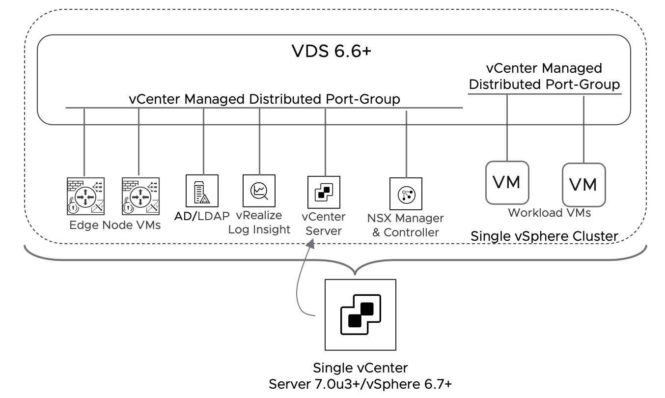
Figure 30: Simple Security - NSX Components and Workload Placement
| # | Design Decision | Design Justification | Design Implication |
| SS.DD.1 | A single NSX Manager will be deployed. | A single NSX manager minimize the resources required to implement the solution. vSphere HA will provide basic level of redundancy to the SDN management and control plane. | During an NSX Manager outage, the NSX Management and Control plane will be unavailable. While the failure will not impact existing flows for already connected VMs, configuration changes will not be possible, new VMs will not have Distributed Firewall rules applied. |
| SS.DD.2 | In vSphere HA, set the restart priority policy for the NSX Manager appliance to high. | NSX Manager implements the control plane for the distributed firewall solution. vSphere HA restarts the NSX Manager appliances first so that other failed virtual machines can receive the correct security policies once they are restored. | If the restart priority for other VMs is set to highest, NSX Manager can take longer to become available and it may impact the effective security policies applied to the restored VMs. |
| SS.DD.3 | Place the NSX Manager appliance on the management VLAN network on a vCenter managed distributed port-group | Provides direct connection to the ESXi hosts and vCenter Server. | An IP address must be available on the Management Network for the NSX Manager Appliance. |
| SS.DD.4 | Place the vRealize Log Insight appliance on the management VLAN network on a vCenter managed distributed port-group | Provides a direct connection to the ESXi hosts and vCenter Server. | An IP address must be available on the Management Network for the vRLI Appliance. |
| SS.DD.5 | Include vCenter Server and NSX Manager in the NSX Distributed firewall exclusion list (If not already included) | Distributed Firewall policies may disable management connectivity to infrastructure management components. While a security policy disabling connectivity to vCenter server can be easily rolled back bypassing the vSphere Client and connecting directly to NSX Manager, a security policy affecting connectivity to NSX Manager requires a more complex recovery procedure and requires contacting VMware Global Services (GSS) | Security protection for vCenter server and NSX Manager is not available. |
Table 5: Scale and Placement of Management Plane Components Design Decisions for the Simple Security Solution
| Management Component | Appliance Size | vCPUs | vRAM | Storage Total GB |
| vCenter Server | Small | 4 | 19G | 694 |
| NSX Manager Virtual Appliance | Medium | 6 | 24G | 200 |
| vRealize Log insight (Not required if another instance is already present) | Small | 4 | 8G | 530 |
Table 6: Management Components Hardware Requirements for the Simple Security Solution
3.3.3 NSX Application Platform (NAPP) Design - Optional
As of NSX Data Center 3.2, VMware has introduced the NSX Application Platform (NAPP). This is a new microservices based solution that provides a highly available, resilient, scale out architecture to deliver a set of core platform services which runs several new NSX features such as:
- NSX Intelligence (Application topology discovery and visualization, security policy recommendation)
- NSX Malware Prevention
- Network Traffic Analysis
- NSX Network Detection and Response
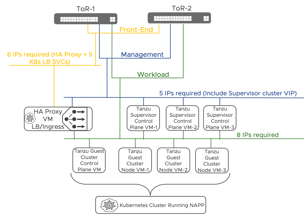
Figure 31: Reference NAPP deployment design for the simple security for application use case
3.3.3.1 High level design Decisions
The table below summarize the design decisions around the NAPP deployment for the simple security for application use case.
| # | Design Decision | Design Justification | Design Implication |
| NAPP.DD.1 | Deploy NAPP on top of a Tanzu Kubernetes Cluster | It provides an end-to-end solution supported by VMware. | A Tanzu Basic license must be available. Additional supervisor cluster VMs must be deployed compared to a solution based on upstream Kubernetes. |
| NAPP.DD.2 | Use Tanzu for vSphere with VDS Networking | It provides an integrated solution with vCenter server, and it does not require NSX networking or overlays This is the only mode supported by the NAPP Automation Appliance. | Three routable VLANs are required An HA Proxy Load Balancer VM is deployed |
| NAPP.DD.3 | Use the NAPP Automation Appliance to deploy Tanzu and NAPP | The NAPP automation appliance provides end-to-end automation of the set-up process with minimal user inputs required. It is also useful for troubleshooting and day 2 operations once the solution is in place. | The NSX Automation Appliance is packaged as a dedicated VM which must be deployed as part of the solution. |
Table 7: NAPP High Level Design Decision
3.3.3.2 Compute and Network requirements
The table below summarizes the compute requirements of the NAPP deployment for the simple security for applications use case. A total of 9 VMs must be deployed. At least a storage policy must be available. If VSAN is part of the solution, we can use the default VSAN storage policy. We can use a tag-based policy instead if external storage is in place.
| Management Component | # | vCPUs | vRAM | Storage Total GB (Thin Provisioned) |
| Supervisor Control Plane VMs | 3 | 4 | 16G | 32 GB |
| TKC Control Plane VM | 1 | 2 | 8G | 328 GB |
| TKC Node VMs | 3 | 16 | 64G | 1128 GB |
| HA Proxy | 1 | 2 | 4G | 20 GB |
| NAPP Automation Appliance | 1 | 1 | 4G | 10 GB |
| Total | 9 | 51 | 256G | 3838 GB |
Table 8: Compute requirements for NAPP
The table below summarizes the network requirements of the NAPP deployment for the simple security for applications use case. Three new dedicated VLANs and subnets must be available and should not be shared with any other component (Not a hard requirement, but it simplifies the IP allocation schema). The physical network must route the three new subnets. They should have connectivity to the Virtual Infrastructure components (vCenter, NSX Manager, and ESXi hosts) and the Internet (Connectivity to the public registry hosting the NAPP images). We can place the NAPP automation appliance on any network as long as IP connectivity to NSX Manager, vCenter, and the Tanzu Kubernetes Cluster is available. The preferred location is the management network where NSX Manager and vCenter reside. vCenter requires connectivity to the Internet to download the Tanzu image library.
| Network | Range Size | Routable | Internet Connectivity | dvpg with the same VLAN ID |
| TKG Management | /27 or more | Yes | No | Yes |
| TKG Workload | /27 or more | Yes | Yes | Yes |
| TKG Front-End | /27 or more | Yes | No | Yes |
Table 9: New networks required for NAPP deployment
3.3.3.3 Sample NAPP Deployment IP Allocation
In this section we provide an example based on the following three subnets:
| Network | Range | Gateway |
| TKG Management | 10.114.209.0/27 | .1 |
| TKG Workload | 10.114.209.32/27 | .33 |
| TKG Front-End | 10.114.209.64/27 | .65 |
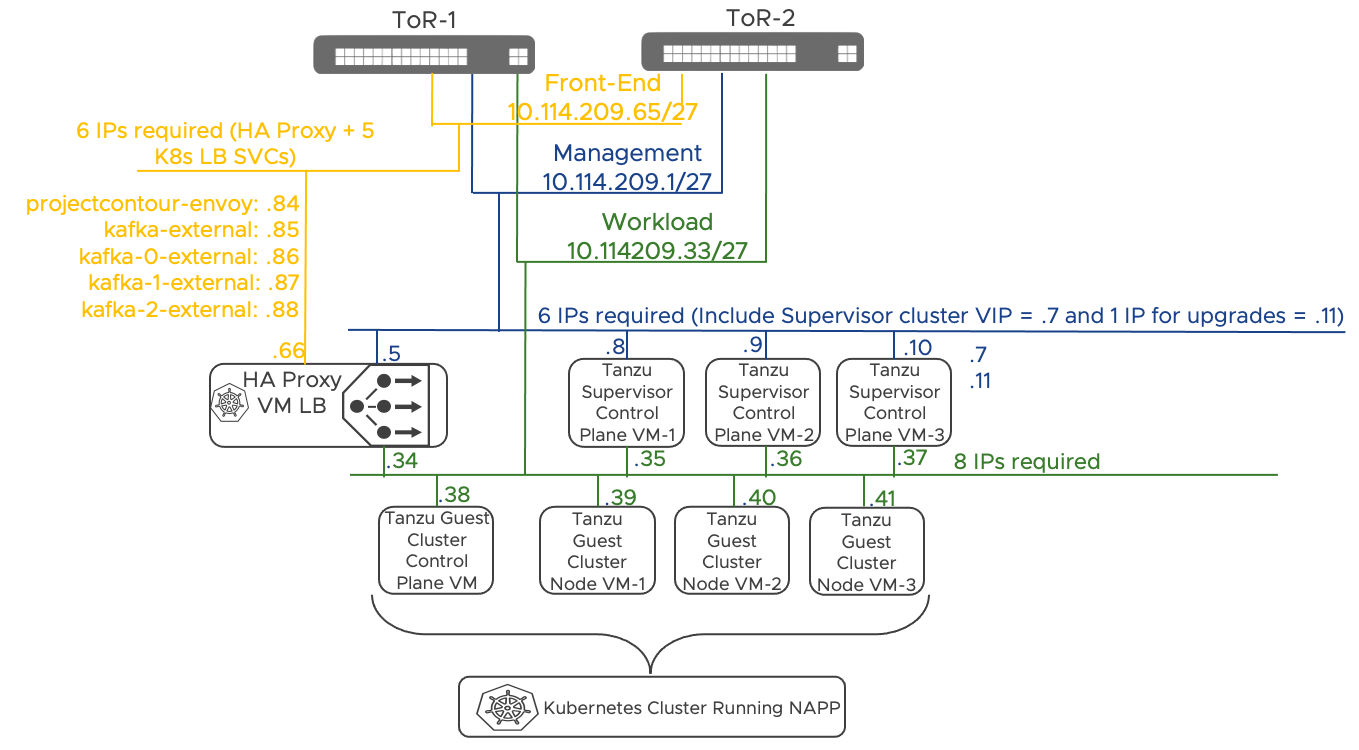
Figure 32: Sample NAPP IP Allocation
3.3.3.4 Reference Resources
NSX Application Platform Automation Guide
A document that covers how to use the NSX Application Platform Automation Appliance to fully automate a NAPP deployment. This included the required microservices environment using a UI based workflow that integrates directly into NSX Manager and only needs the required infrastructure to be provided (vSphere 7.0, compute, network and storage resources):
NSX Application Platform Automation Guide
NSX Application Platform Automation Appliance
The virtual appliance (OVA) referenced in the Automation Guide.
NSX Application Platform Automation Appliance
NSX Application Platform Deployment Guide
A detailed step-by-step guide on how to deploy NSX Application Platform aligned to VMware recommendations and best practices.
NSX Application Platform Deployment Guide
3.4 Data Center in a Box Solution Design
This design is intended to incorporate a small to medium sized hardware footprint of between two and fifty hosts and is limited to the boundary of a single set of Top of Rack (ToR) switches. As such, the workload should fit inside of these boundaries and have under 1000 Virtual Machines.
3.4.1 Assumptions
The solutions in this document make a set of assumptions about the physical networking, compute hardware, and supporting services. We made these assumptions to simplify the deployment and enable a quick path to consumption of the use cases addressed by the solutions. Before modifying one of these configurations or assumptions that are described, it is recommended that an evaluation is performed to determine if the benefit of modifying the solution outweighs the additional effort that it may require.
3.4.1.1 Physical Network Assumptions
A base set of assumptions are made about physical networking to simplify the solutions in this guide. Those assumptions are detailed in the table below but briefly summarize them here.
The physical network is limited to two top-of-rack switches, which may or may not provide layer three functionalities. Layer 2 only configurations are supported as long as VLAN trunking and jumbo frames capabilities are available. As with any vSphere deployment, 3 VLANs for ESXi VMKernel traffic are recommended. Those VLANs segment management, vMotion, and storage traffic. On top of those 3 VLANs, the DC in a Box solution requires two additional VLANs, one for Overlay traffic and one for the physical network's interconnection to the virtual network. The Overlay VLAN does not need routing capabilities. The physical to virtual VLAN transit can be implemented as layer two when the DC in a Box connects to the Internet directly. It may require a layer three gateway when the ToR switches act as the external network. The diagrams below outline the two scenarios.
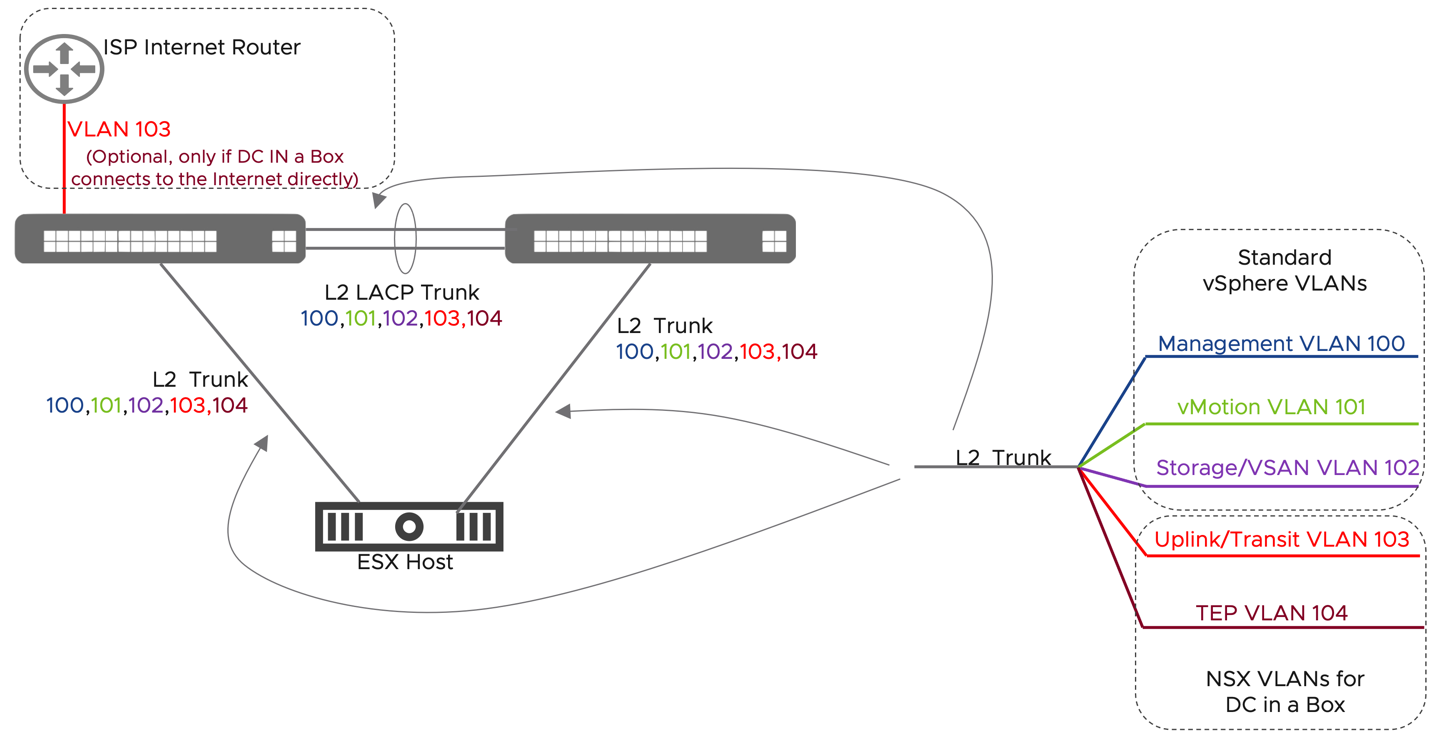
Figure 33: DC in a Box - Physical Network Assumptions, untrusted external network
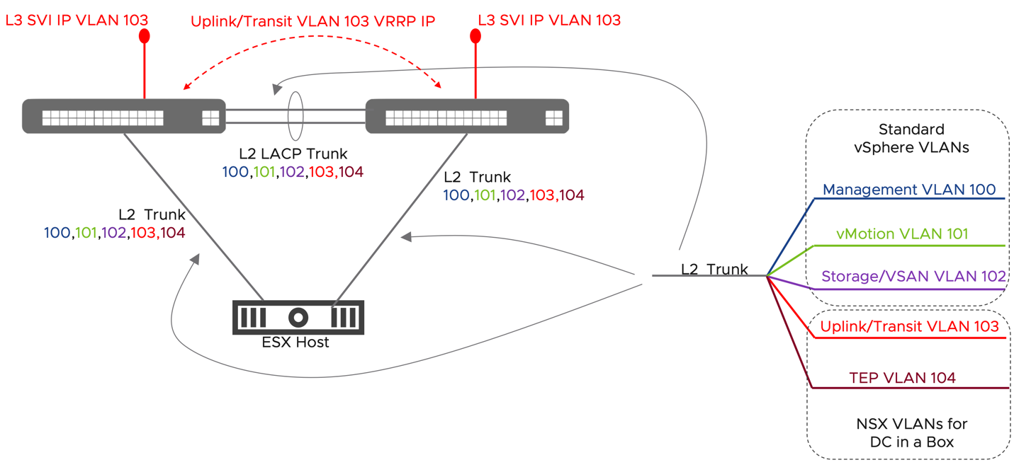
Figure 34: DC in a Box - Physical Network Assumptions, trusted external network
| # | Assumption | Description | Justification |
| DB.AS.1 | Single ToR Pair Design with the ability to extend VLANs between them | This design assumes that the physical servers making up this environment all sit under a single redundant pair of switches. Supports the use of two 10 GbE (25 GbE or greater recommended) links to each server, provides redundancy and reduces the overall design complexity. | Decreased complexity around L2 vs L3 communication between components and a simplification of the overall design |
| DB.AS.2 | Critical Network Services are Available | Critical Network Services are already available and running outside of this environment. Those services include: NTP, DNS, an LDAP Authentication Source, and SYSLOG or Log Insight logging destination. | While it is not mandatory that these services run outside of the environment, to simplify the deployment, this is the expectation. |
| DB.AS.3 | MTU for TEP Network | The MTU on the TEP Network is set to 9000 in NSX. The ToR Switches should be configured to match. If a lower size is chosen, it must be consistent and at least 1700. | The overlay network is created using a set of Geneve Tunnels between Transport Nodes. |
| DB.AS.4 | The management Network is provided by the physical infrastructure and must be extended between the two ToR switches | A management VLAN is configured on the two ToR switches. The management network of the deployed NSX components must be placed on the underlay network. | The NSX Manager and the Edge Node VMs must be connected to VLANs rather than on Overlay to avoid recursive dependencies |
| DB.AS.5 | 3 IP Addresses available on the Management Network | 3 IP addresses are required for the management interfaces of the single NSX Manager and the two NSX edge nodes VMs. | Management network connectivity is required for all NSX components |
| DB.AS.6 | New Transit VLAN and Subnet (/28 or larger) | This VLAN is dedicated to traffic between the Physical Network and the NSX Edge Nodes. This network will include the range of NAT IPs used to access instances in the DC in a box. A larger subnet will allow for more VMs to be directly accessed. The minimum size /28 range allows for 7 VMs to be reachable on unique IPs. The VLAN must be routable only if the ToR switches are connecting to the external network. For example in the case where the ToR switches are connected to a larger datacenter netwok or a private WAN circuit. If the DC in a Box is isolated and linked to an untrusted network (i.e., the Internet), the ToR will only need to provide Layer2 transport. See the Layer 3 logical design for more details about the two options. | Isolating the physical to virtual traffic in a dedicated broadcast domain reduces the risk of inadvertently affecting it during normal operations. |
| DB.AS.7 | New non routable TEP VLAN and Subnet (/24) | A new /24 IP range and VLAN must be assigned for the tunnel end point interfaces on the ESXi hosts and Edge VMs. It is not required to configure a default gateway on the ToR switches. DHCP is not required for this VLAN. NSX manager will assign the TEP IPs from a configured Pool. | Tunnel Endpoint interfaces (TEPs) are required for network virtualization. Hosts and Edge VMs only create Geneve tunnel with one another, so there is no need to route the network externally. Besides simplifying the physical network configuration, isolating the TEP network provides a simple but effective way of securing the overlay network from external tampering. |
Table 10: Physical Network Assumptions
3.4.1.2 Compute Assumptions
For the solutions described in this document, a set of assumptions have been made about the compute environment. These assumptions cover the physical ESXi servers themselves.
| # | Assumption | Description | Justification |
| DB.AS.8 | Network Adapters in the Compute Hardware is fully supported by NSX | VMware and the Hardware Vendors work together to generate an IO Devices Compatibility List which specifies the specific components that are supported with what features and at what driver and firmware levels. NSX specifically calls out set of features required for Network Adapters to achieve the expected performance levels. Please follow the guidance in Section 8.4 of the NSX Reference Design Guide for which features are required and how to validate that they are available. | Network adaptor support for overly offload and enhancements are mandatory for NSX virtualization performance |
| DB.AS.9 | Each vSphere host has two (2) pNICs available to ESXi and a single VDS. | In all designs inside leveraging this foundational hardware platform, it is assumed that each host will have a single VDS configured with two pNICs assigned to it. This VDS will be used for in-band management and data plane traffic. Out-of-Band Management traffic such as an IPMI, ILO, CIMC, or iDRAC interface is specific to the hardware vendor and out of scope for this design. Remote management capabilities of the physical server is however highly recommended for operational reasons. | The justification for two (2) pNICs specifically in this design is based on DB.AS.11 below from a redundancy and availability perspective. This solution can be extended for 4 pNICs to address isolation and performance requirements. However the scenario is not covered to adhere to a simple and general use case |
| DB.AS.10 | Shared Storage is available to all Compute Hardware in a Cluster | NSX Manager and NSX Edge Node VMs should remain available on persistent storage even in the event of a physical server failure and be automatically recovered through a service like vSphere High Availability in the unlikely event. While NSX does have capabilities to address these types of failures without shared storage, this document for simplicity of deployment and operations will assume that there is shared storage. | This document does not address the methods of recovery from data loss in the event of single host failures. As a result, it assumes all hosts in a single cluster are connected to shared storage allowing for VM Level recovery to other nodes in the cluster leveraging vSphere’s Distributed Availability Service (HA) |
| DB.AS.11 | Component level redundancy is built into each Compute Node | A base level of availability should be built into every hardware component of this system. This includes:
Redundancy at the RAM, Disk Controller, and other layers may be implemented if deemed necessary. | When an individual component failure can bring down a portion of the environment, ensuring that all reasonable steps are taken to prevent those failures and ensure the availability of the system as a whole |
| DB.AS.12 | Scale Requirements, Two Host Minimum and 50 Host Maximum | There is a two-host minimum configuration for solutions in this document. There is also an intended maximum of 50 nodes. | The scale limitation is imposed at the floor by the requirements for availability and reducing the single points of failure in the environment. At the ceiling, this design is bound by the limitations of a single Top of Rack (ToR) switch pair. |
Table 11: Compute Assumptions
3.4.1.3 Virtual Environment Assumptions
The solutions in this document all assume a vSphere 7.x based environment inside a single vSphere Cluster which is used in a homogenous manner to present hosting, network, and security services to the workloads that run on top of it. This type of environment from an NSX perspective is called a Fully Collapsed Cluster design. It is called this because Management Workload for the environment, Production Workload running on the environment and any network and security services provided to the workloads running on the environment will all be hosted on a single cluster. To enable this design the follow assumptions for the virtual environment are made.
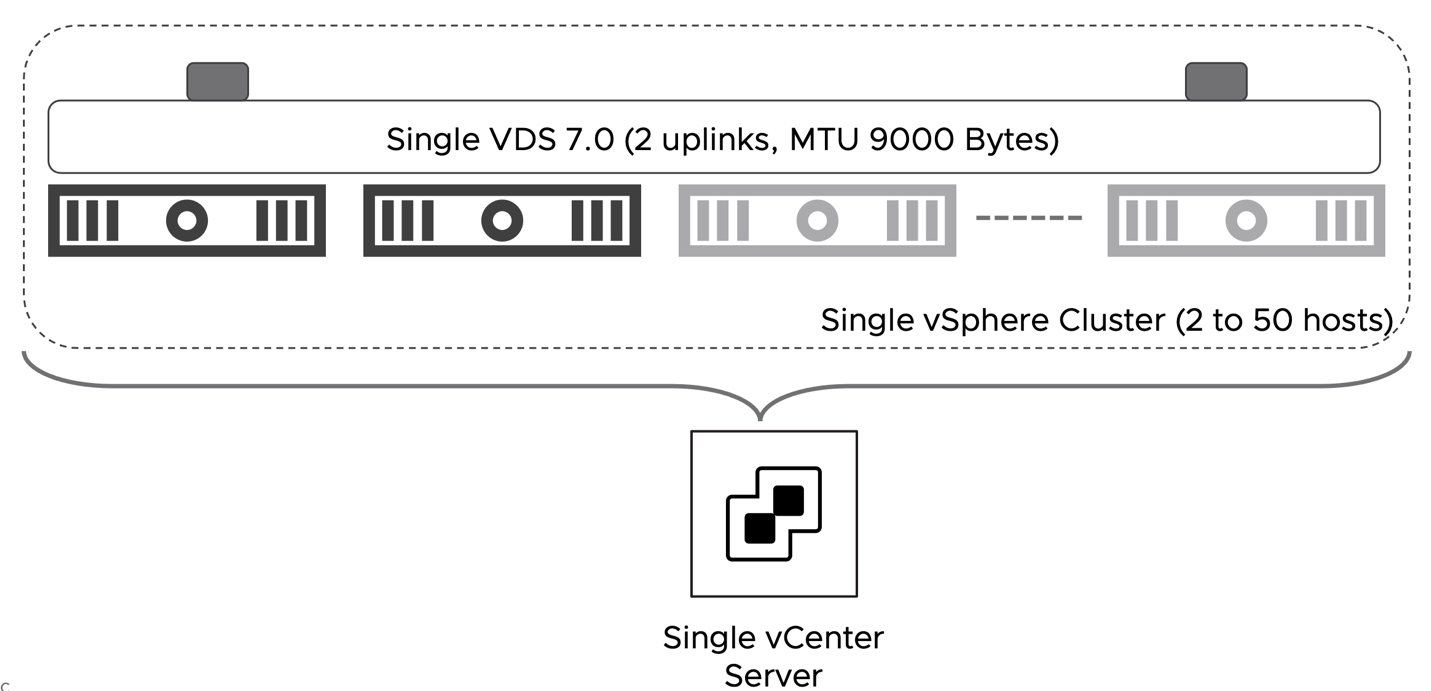
Figure 35: DC in a Box - Virtual Environment Assumptions
| # | Assumption | Description | Justification |
| DB.AS.13 | The vSphere environment is running version 7.0u3 or later. | The vCenter server and the ESXi hosts are running on the software version 7.0u3 or later | vSphere 7 is required to dramatically simplify the implementation of NSX on a collapsed cluster design by leveraging VDS 7. Patch levels later than 7.0u3 will most likely work but have not been validated. |
| DB.AS.14 | vCenter Server appliance deployment size at least small. | The small size vCenter appliance can support up to 100 hypervisors and 1000 VMs. | The small size can support up to upper boundary of the solution in scope. |
| DB.AS.15 | vCenter Server is deployed on the Management Network VLAN and connected to a vCenter managed dvpg. | vCenter server connectivity is provided by the physical network and completely independent from NSX. | Provides direct secure connection to the ESXi hosts and NSX Manager. Remove any dependency on NSX networking. |
| DB.AS.16 | Collapsed Cluster Design | Single vSphere collapsed cluster where Management appliances, NSX Edge Node VMs, and Workloads all reside on the same cluster. | Maximizes available resource utilization. |
| DB.AS.17 | Single VDS 7.0 with two uplinks | A single VDS of must be present in the cluster. The VDS version must be 7.0. | VDS allows the implementation of NSX services without deploying an additional virtual switch (NVDS). It also simplifies the collapsed cluster design by allowing for the placement of the management appliances on vCenter managed port-groups. |
| DB.AS.18 | VDS MTU set to 9000 Bytes | When NSX integrates with VDS the MTU value is inherited from the VDS. The NSX Uplink profile must not have any value for the MTU setting. | 9000 is the maximum supported in vSphere. It should match value set on the physical network. |
| DB.AS.19 | vSphere HA is enabled | Use vSphere HA to protect all virtual machines against failures. | vSphere HA supports a robust level of protection for the NSX components availability. |
| DB.AS.20 | NTP server is available | vCenter and the ESXi hosts are synchronized to a reliable NTP server. | Firewall logs are generated by the ESXi servers. NTP synchronization ensures that the timestamps are accurate. |
Table 12: Virtual Environment Assumptions
3.4.1.4 Access and Authentication Assumptions
A critical component for any environment meant to host production workloads is its ability to control, track, and provide access to those teams and systems that need to access the environment. NSX provides a granular role-based access control capability through integrations with enterprise grade authentication directories. One requirement is to configure the integration between NSX Manager and vCenter Server with a corporate directory that meets the organization’s requirements for security and compliance. It is recommended to tie the built-in roles in NSX to groups in your corporate directory where they match responsibilities of existing teams for this environment. In this design NSX will be directly integrated with Microsoft AD.
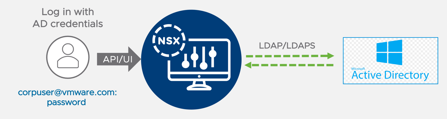
Figure 36: NSX Active Directory Integration
| # | Assumption | Description | Justification |
| DB.AS.21 | Microsoft Active Directory exists, and it is reachable from NSX Manager | NSX Manager will query the Microsoft Active Directory to authenticate user access to the UI or the API. | MS Active Directory is the most common directory service in SMEs. Also, the direct integration between NSX and MS Active Directory is the easiest way to provide NSX administrative access based on corporate users and groups as it does not require the deployment and configuration of additional components (i.e., Workspace ONE Access). |
| DB.AS.22 | AD groups and user definition mapped to NSX pre-defined roles | To provide NSX role-based access control RBAC, AD groups and user definitions must be mapped to NSX pre-defined roles | The use of pre-defined NSX role simplifies the adoption of RBAC compared to the adoption of custom roles. More sophisticated RBAC implementation can be adopted subsequently. |
Table 13: Access and Authentication Assumptions
3.4.2 NSX Design
3.4.2.1 Scale and Placement of Management and Data Plane Components
The Management Components in this solution are the vCenter Server Appliance, NSX Manager Appliance, and vRealize Log Insight. While native HA/Clustering solutions are available for them, we are leveraging vSphere High Availability for their availability profile in this design. While this design assumes that these components will live inside the single vSphere cluster hosting all the workloads, it is fully supported to run them elsewhere.
Note: The deployment of a dedicated instance of vRealize Log Insight is not required if a centralized instance is already present or another logging solution is in place.
Two medium-size Edge node VMs provide the physical to virtual connectivity in this solution. Besides layer three routing, the edges are sized to support additional services such as NAT, Gateway firewall, and VPN.
The default MTU value of 1500 Bytes for the edge interface is not modified. North/South throughput performance will be dependent on the specific traffic pattern and the underlying hardware on top of which the solution is deployed. For a more in-depth analysis of the performance that can be achieved by an Edge Node VM and the performance tuning and optimization available, please consult the NSX Design Guide.
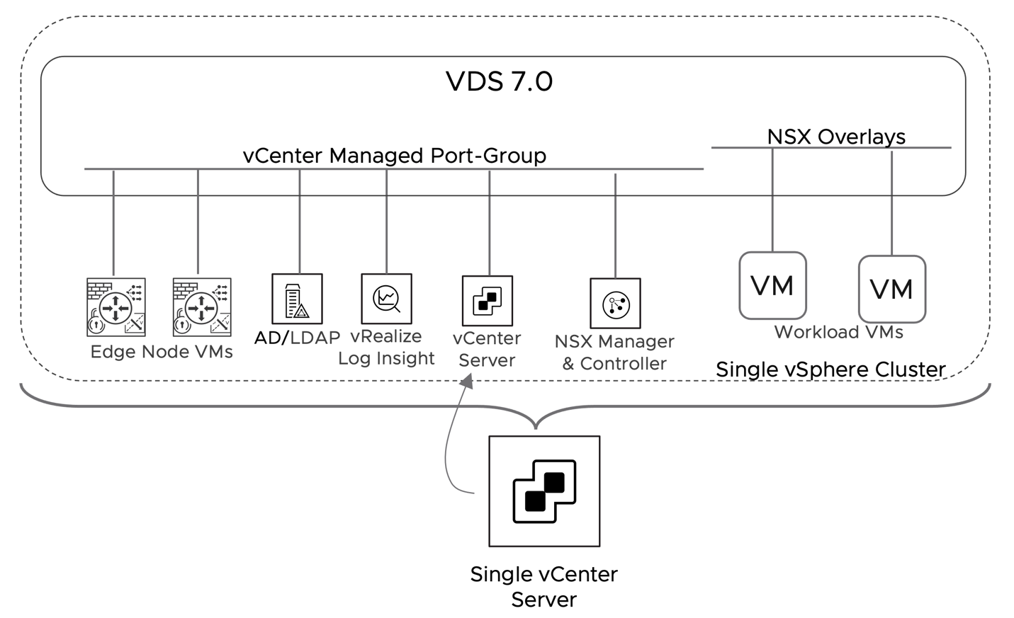
Figure 37: DC in a Box - NSX Components Placement
| # | Design Decision | Design Justification | Design Implication |
| DB.DD.1 | A single NSX Manager will be deployed. | A single NSX manager minimize the resources required to implement the solution. vSphere HA will provide basic level of redundancy to the SDN management and control plane. | During an NSX Manager outage, the NSX Management and Control plane will be unavailable. While the failure will not impact existing flows for already connected VMs, configuration changes will not be possible, new VMs may not be able to connect to the network, and vMotion will not be available for workloads connected to NSX Segments. |
| DB.DD.2 | In vSphere HA, set the restart priority policy for the NSX Manager appliance to high. | NSX Manager implements the control plane for virtual network segments. vSphere HA restarts the NSX Manager appliances first so that other failed virtual machines can connect to the network once they are restored. | If the restart priority for other VMs is set to highest, NSX Manager can take longer to become available. VMs restored before NSX Manager may not have connectivity until it is up. |
| DB.DD.3 | Place the NSX Manager appliance on the management VLAN network on a vCenter managed distributed port-group | Provides direct secure connection to the ESXi hosts and vCenter Server. | An IP address must be available on the management network. |
| DB.DD.4 | Place the vRealize Log Insight appliance on the management VLAN network on a vCenter managed distributed port-group | Provides direct secure connection to the ESXi hosts and vCenter Server. | IP address must be available on the management network. |
| DB.DD.5 | Deploy two Edge Node VM with a size of medium | Two Edge Node VM provide HA. If one fails, the second will automatically take over the network forwarding and services ownership. The medium form factor limits the footprint of the solution in a small environment. | A medium size Edge Node VM provides limited performances. Environments requiring more than 2G of North/South traffic should consider deploying a large form factor instead. |
| DB.DD.6 | Deploy the two Edge node VMs on different hosts. | Keeps the NSX Edge nodes running on different ESXi hosts for high availability. | If DRS is enabled, the edge Node VMs will be subject to vMotion by DRS during normal operations and may be placed on the same host. Configure the appropriate DRS rule to avoid this scenario. |
| DB.DD.7 | Place the NSX Edge Node VM management interface on the management VLAN network on a vCenter managed distributed port-group | Provides direct secure connection to NSX Manager. | IP addresses must be available on the management network. |
Table 14: Scale and Placement of Management Plane Components Design Decisions for the DC in a Box Solution
| Management Component | Appliance Size | vCPUs | vRAM | Storage Total GB |
| vCenter Server | Small | 4 | 19G | 694 |
| NSX Manager Virtual Appliance | Medium | 6 | 24G | 200 |
| Edge Node VM - 1 | Medium | 4 | 8G | 200 |
| Edge Node VM - 2 | Medium | 4 | 8G | 200 |
| vRealize Log insight (Not required if another instance is already present) | Small | 4 | 8G | 530 |
Table 15: Management and Data Plane Components Hardware Requirements
3.4.2.2 Transport Zones and Layer 2 design
Transport zones define the span of VLAN or Overlay Segments in NSX. In this solution, we will use a single Overlay transport zone encompassing all hosts and edges. This will make the overlay networks available on all the hosts where workloads reside and on the edge nodes, which will provide network services to those overlay segments.
Underlay VLAN connectivity requirements will be different for the hosts and the edge nodes. For this reason, we will configure two separate VLAN Transport Zone.
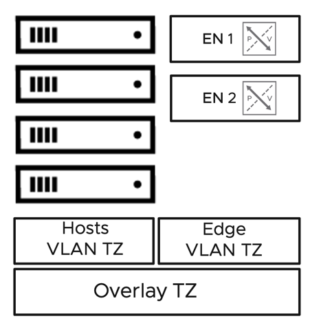
Figure 38: Transport Zone Layout
VLAN TZ defines which VLAN segments are available on the virtual switch of the associated transport node. The ESXi hosts require two Trunk Segments to which the Edge Nodes will be connected. The virtual switch on the Edge Nodes will have only the uplink VLAN defined. The organization may add additional VLANs in the future to implement service-interfaces that can be leveraged to extend the NSX security coverage via the NSX Gateway Firewall to virtual machines not in the NSX domain or bare metal servers. An example would be a service interface to interconnect the physical infrastructure management network if the DC in a box was only reachable via an untrusted connection such as the Internet (See Layer 3 section).
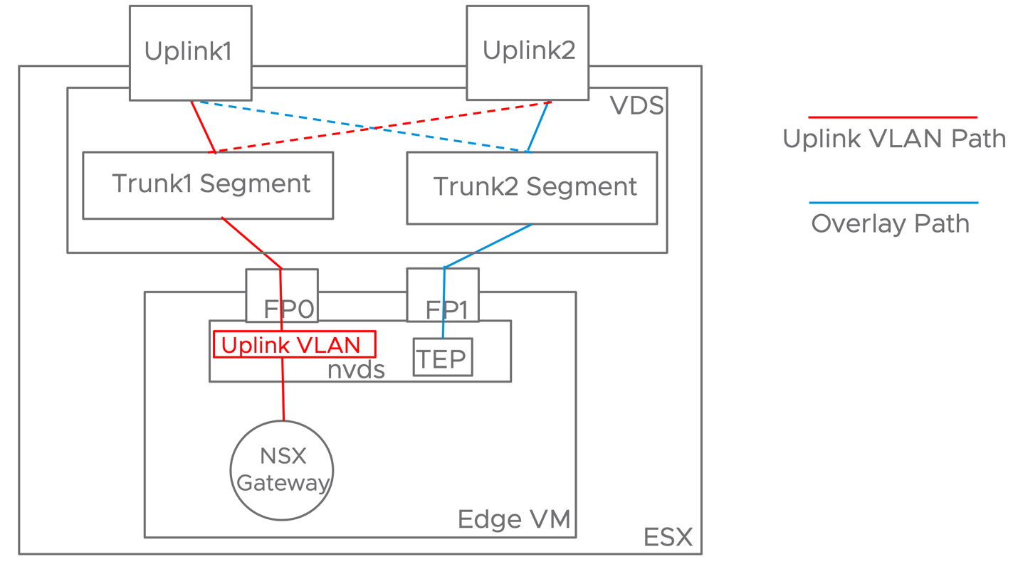
Figure 39: Virtual Switch Design
The uplink VLAN will only use one of the fast-path interfaces on the Edge Node VMs. The uplink traffic is forwarded to the first ESXi physical NIC by the first Trunk Segment on the VDS. The first Trunk Segment is connected to the FP0 interface of both edge node VMs and configured with a Failover Teaming policy. In case of a failure of the first Uplink connected to the ToR switch 1, the VDS will redirect the uplink traffic over Uplink2 to the ToR switch2. The loss of an ESXi host physical NIC is transparent to the NSX Edge Node.
Similarly, the Edge Node Overlay traffic originated by the TEP interface on the NVDS is forced out of the second fast-path interface on the edge node VM. From there, the TEP traffic is handled by a Trunk Segment on the VDS, which will forward it on the Physical link to the ToR switch two unless a failure occurs.
This configuration allows for symmetrical utilization of the physical uplinks by the North/South traffic.
| # | Design Decision | Design Justification | Design Implication |
| DB.DD.8 | A single Overlay Transport Zone will be configured | A single Overlay Transport Zone provides maximum flexibility in placing workload anywhere on the cluster. A Transport Zone should not be considered a security boundary, but as a hard boundary to physically segment resources between different tenants. Because maximum flexibility and optimal resource utilization is one of the goals of the solution, a single overlay transport zone is in use. | None |
| DB.DD.9 | Two separate VLAN transport zones are configured for hosts and edge transport nodes respectively. | Hosts and edge nodes have different VLAN definitions and named teaming policy requirements. Separating them will improve manageability. | An additional configuration object is created |
| DB.DB.DD.10 | Use a single uplink VLAN between the physical network and the NSX Gateway | A single transit network simplifies the connectivity between the physical and the virtual environment. | Traffic from the NSX Gateway can be forwarded by a single physical uplink at the time. The transit VLAN must be extended between the two ToR switches making it susceptible to spanning-tree or other layer two instabilities. This solution prioritizes simplicity and ease of adoption, so the trade-off is considered acceptable. The symmetric pinning of the overlay traffic to the second uplink mitigates the performance concern. |
| DB.DD.11 | Pin underlay and overlay traffic to different fast-path interfaces on the edge VMs | Outbound virtual to physical traffic is generated on the single nvds port where the NSX Gateway uplink is connected. This implies that a single Edge Node vNic will be used regardless of the teaming policy in use. Pinning the traffic to a specific vNic makes the configuration deterministic. | Overlay traffic uses only one of the uplinks. Because the underlay traffic symmetrically uses the other, it should not represent a performance impairment. |
| DB.DD.12 | Configure the Trunk dvpg where the Edge Node VMs connected with a mirrored Active/Standby teaming policy | A failure on the VLAN connectivity side will not be detected by the edge node VM because nor dynamic routing nor BFD are included in this solution (See Layer3 section). The upstream VDS teaming policy should prevent the traffic to be black holed in case of a physical NIC failure. | In case of a ESXi pNIC failure, underlay and overlay edge traffic will share the same ESXi pNIC causing potential performance degradation. For this solution, we accepted the potential performance degradation to maximize high availability. |
Table 16: Transport Zones and Layer 2 Design Decisions
3.4.2.3 TEP network Design
In this design we have a single TEP network shared between the hosts and the Edge Node VMs. Hosts have a multi-TEP configuration where the overlay traffic is load balanced across the two pNICs based on the port ID of the originating VM. Edge node VMs have a single TEP configuration pinned to the second fast-path vNic.
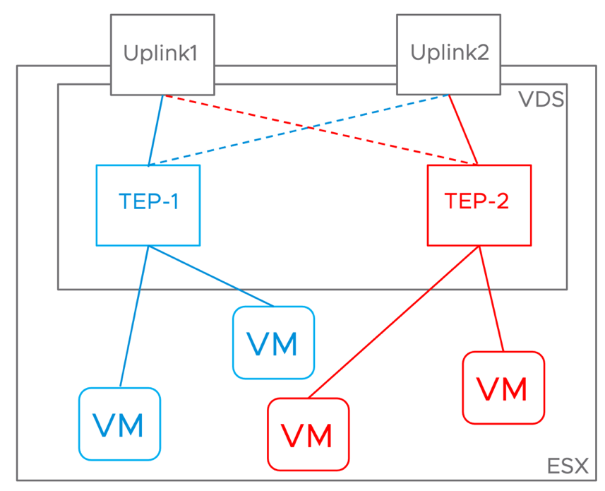
Figure 41: Host TEP Design
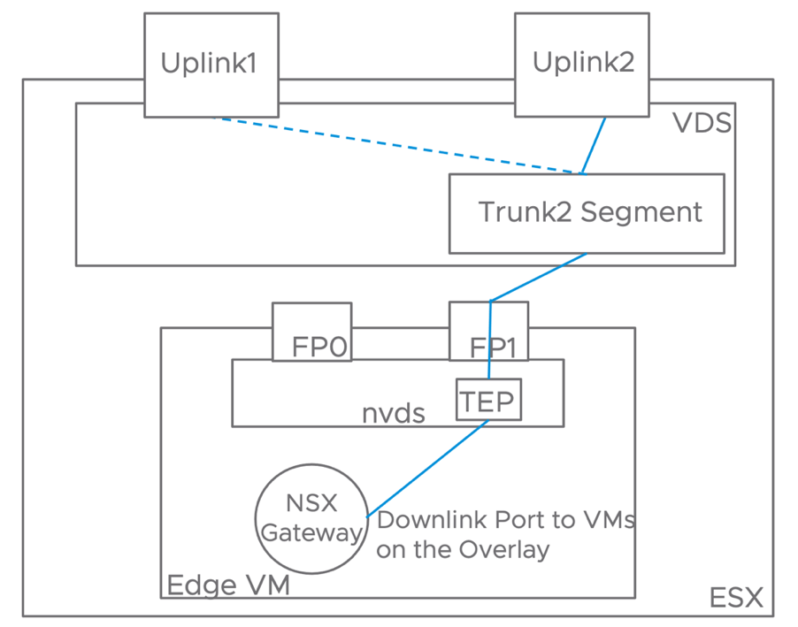
Figure 42: Edge Node TEP Design
| # | Design Decision | Design Justification | Design Implication |
| DB.DD.13 | Host and Edge Transport Node shares the same TEP VLAN and network | A single TEP network design dramatically simplifies the required physical network configuration. In the context of this solution, this simplification represents a valuable benefit. The single TEP network design removes the need to configure routing between different TEP networks, providing FHRP for them, setting the MTU on the L3 interface, and securing them (i.e., via ACL or VRF on the ToRs) | Sharing the TEP network between Hosts and Edges may limit the ability to move Edge nodes between racks. In the context of this solution, it does not represent a problem as we have a single rack design. |
| DB.DD.14 | Use load-balancing based on originating port id teaming policy for host overlay traffic | Workloads East-West Traffic is load balanced across the two pNIC on each host, driving better uplink utilization while preserving implementation simplicity. While LACP would provide similar traffic management benefits, it has not been selected to avoid any physical network dependency and configuration complexity. | Each host requires one IP address on the TEP subnet for each pNIC. In this solution we require a /24 to be allocated. 254 IPs are enough to support the upper boundary of 50 hosts with 2 pNICs each. |
| DB.DD.15 | On the Edges, use a single TEP, active on a single vNIC. | The Edge VLAN traffic is pinned to the first edge vNIC and host pNIC. Overlay traffic has symmetric resources available on the other vNIC and pNIC. Load balancing overlay traffic, while possible, may impair performance instead of benefiting them. Providing a deterministic path for the Overlay traffic improves manageability by making troubleshooting easier. | This represents a deviation from the standard design presented in the NSX Design Guide. A single TEP design is less effective at consuming the available CPU resources on the Edge VM. |
Table 17: TEP Network Design Decisions
3.4.2.4 Layer 3 Logical Design
The NSX Gateway is the core Layer 3 component of the Datacenter in Box solution. It provides routing capabilities between the DC in a box networks and the external network. We minimize the interaction between the NSX Gateway and the external network to reduce any dependency and make introducing the DC in a box solution as seamless as possible regardless of the external network characteristics or capabilities.
The DC in a box may be connected to a simple Internet broadband connection. The only requirement is that enough Public IP addresses are available. This document assumes that the minimum publicly routable subnet is a /28 (14 Available IP addresses). This requirement derives from allocating IPs to the NSX components while still having a reasonable number of IPs to expose workload to clients over the Internet. Below is an example of how a sample /28 may be allocated, assuming that the ISP only consumes 1 IP for the gateway.
| IP | Used For |
| 10.255.255.0/28 | Network IP Address – Not Available for use |
| 10.255.255.1 | NSX Gateway - Active Edge |
| 10.255.255.2 | NSX Gateway - Standby Edge |
| 10.255.255.3 | NSX Gateway – SNAT IP (Used for General Outbound Connectivity from the DC in a Box) |
| 10.255.255.4 | NSX Gateway – VIP IP (Required to expand the range via Static Routes) |
| 10.255.255.5 | Available for Inbound Connectivity |
| 10.255.255.6 | Available for Inbound Connectivity |
| 10.255.255.7 | Available for Inbound Connectivity |
| 10.255.255.8 | Available for Inbound Connectivity |
| 10.255.255.9 | Available for Inbound Connectivity |
| 10.255.255.10 | Available for Inbound Connectivity |
| 10.255.255.11 | Available for Inbound Connectivity |
| 10.255.255.12 | Available for Inbound Connectivity |
| 10.255.255.13 | Available for Inbound Connectivity |
| 10.255.255.14 | ISP Gateway IP |
| 10.255.255.15 | Broadcast IP Address – Not Available for use |
Table 18: Example of IP Allocation for a Routable Range
In this example, with a /28, we have nine IPs available to expose workload to the external world. Some ISPs provide a /29 by default. While usable, a /29 allows for a single workload to be exposed. If the ISP is unwilling to expand the subnet, they can usually accommodate by allocating an additional non-contiguous range. In that case it is sufficient they point the new range to the NSX Gateway VIP (10.255.255.4 in our example) via a static route. Once done, you will have the range available to expose additional workload without changing the DC in a Box solution.
When connected to an untrusted network such as the Internet, the NSX Gateway will also provide access to the underlying infrastructure components such as the ToR switches, NSX Manager, vCenter. By default, those components will only be accessible from the DC in a Box internal subnet. Even if it is not recommended, the NSX Gateway can be configured to allow direct access from the Internet to the management infrastructure. A logical layout of this overall configuration is outlined below.
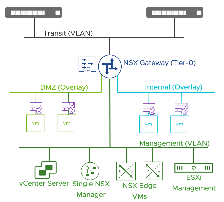
Figure 43: Logical Layer 3 Diagram when DC in a Box in connected to an Untrusted External Network
In some scenarios, we connect the DC in a box to the existing infrastructure: a new rack in an existing data center, or a new location connected via a private, trusted connection (i.e., a private p2p link or a provider-managed MPLS circuit). In this scenario protecting the infrastructure components via the NSX Gateway Firewall capabilities may not be required. They can be safely placed on the external network from the perspective of the DC in Box. A logical layout for this option is presented below.
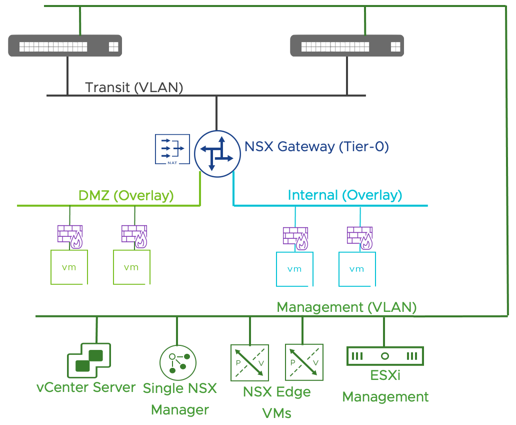
Figure 44: Logical Layer 3 Diagram when DC in a Box in connected to a Trusted External Network
When we connect the DC in a Box to a trusted external network, some infrastructure components such as AD/LDAP, vRLI, NTP, and DNS can be deployed outside of the single vSphere cluster part of the solution. They can even be located at a different site if we can provide reliable connectivity. vCenter Server and NSX Manager must instead be deployed within the DC in a Box solution and not shared by any other infrastructure resource.
When connecting to a trusted internal network, the physical network administrator plays the role of the Internet Service provider. In this situation, we do not require public IP addresses. Still, the network administrator must assign an internally routable range (again /28 or larger) where the DC in Box owner can expose workloads. IP address schema within the DC in a Box is independent of the external network, even if private. The DC in a Box owner can freely assign IP addresses without worrying about conflicts.
Note: Connectivity issues may still arise when connecting the DC in a Box to a trusted network if the client IP belongs to one of the ranges assigned to the DC in a Box network. Unique IPs or IPs duplicated to systems that do not require access to the DC in a Box will solve the problem.
| # | Design Decision | Design Justification | Design Implication |
| DB.DD.16 | The DC in a Box workload networks are not routable to the external network | Hiding the workload network behind a NAT boundary provides the easiest integration path to a variety of external networks with different characteristics and functionalities. IP Address Management (IPAM) for the workload networks is decoupled from that of the larger enterprise minimizing the need for coordination and resource contention. Relying on NAT and Proxy-ARP minimize the amount of physical network configurations to support the solution. | Some applications do not work when NAT is in the path. Workarounds such as NO-NAT rules are available but outside of the scope of this document. Direct external access to a workload requires the availability of a NAT IP. If the NAT IP range is constrained, workarounds such as jump host or proxy servers should be considered. |
| DB.DD.17 | Define two default workload overlay networks: Internal and DMZ. | The two default workload overlay network are configured to provide a ready for consumption environment. Workload exposed to the untrusted network should be placed on the DMZ network. The Internal network should be used for more critical VMs. A simple zone based security configuration is applied to the workloads connected to those networks (More details in the Security Section) | If a different network layout is desirable, the default workload networks can be deleted and new networks created. |
| DB.DD.18 | Provide the option to protect access to the infrastructure management Network via the NSX Gateway | This option is required when connecting the DC in a Box to an untrusted network. It allows a user logged on a machine on the internal network to access the infrastructure components. | DFW firewall capabilities are not available in the Infrastructure Security Zone. It means that the optional micro-segmentation capabilities available in the internal and DMZ zones are not available for the infrastructure components. |
Table 19: Logical Layer 3 Design - Design Decisions
3.4.2.5 Layer 3 Detailed Design
The NSX Gateway connects to the external network via a single transit network. No dynamic or static routing is required between the external network and the NSX Gateway. Any communication from and to workload in the Data Center in a Box is subject to Network Address Translation on an IP belonging to the transit network.
The Active NSX Gateway uses Proxy-Arp to publish the NAT IPs via the MAC Address of the uplink interface. Proxy-Arp eliminates the need to route the NAT range between the external network and the NSX Gateway. This process greatly simplifies the integration between the external network and the NSX Gateway.
The NSX Gateway runs in Active/Standby to provide rapid recovery of traffic forwarding and network services in case of a failure of the Edge Node or the ESXi host where it is running.
Outbound traffic from the Datacenter in a Box requires the configuration of a default static route on the NSX Gateway pointing to the gateway IP on the external network. The external network should provide first-hop redundancy via VRRP or equivalent protocol.
The NSX Gateway comes pre-configured with a VIP IP. The NAT range can be expanded by adding a static route pointing to the NSX Gateway VIP IP. The static route must be configured on the external network, on both devices, if the external network is redundant such as in the case the ToR switches represent it.
Two default workload networks are created for Internet exposed VMs (DMZ) and internal workloads (Internal).
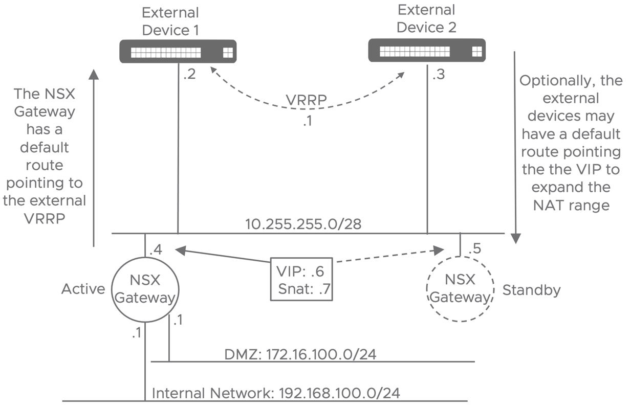
Figure 45: Detailed Layer3 Design
| # | Design Decision | Design Justification | Design Implication |
| DB.DD.19 | Dynamic routing and BFD are not part of the solution. | Excluding advanced routing capabilities from the design simplifies the requirements on the physical network and facilitate day-2 operations for the Administrator. | Optimal levels of high availability are achieved via dynamic routing and BFD. |
| DB.DD.20 | A single Default Static route is configured on the NSX Gateway. | Required to route the DC in a box outbound traffic to the external traffic. | The external network should implement a first hop redundancy protocol (FHRP) to increase high availability |
| DB.DD.21 | NAT is performed via Proxy-Arp | Proxy-Arp remove the need to configure any type of routing on the external network, simplifying the physical network assumptions and configuration. | Using many Proxy-Arp entries is not scalable. If the number of DNAT configuration increased, it may be required to move to a routed configuration (see DB.DD.23) |
| DB.DD.22 | Provide a single SNAT IP for all the Datacenter in a Box outbound traffic. | Provide and easy out of the box solution for outbound connectivity | External components such as physical firewall will see the traffic from any VM in the DC in a Box originating from the same IP. Additional SNAT IP can be configured if external systems require to identify the workload based on their IP. |
| DB.DD.23 | Configure a VIP on the uplink Interface of the NSX gateway. | Not used by default, but it allows the expansion of the NAT range via static routes configured on the external network devices (ISP routers or ToR switches) | If not used, the VIP waste an otherwise available NAT IP. It can be deleted. |
| DB.DD.24 | The NSX gateway consists of a single Tier-0 Gateway | A single tier topology provides all the functionalities required in the DC in a Box solution while preserving simplicity. The DC in a Box in a single tenant manually operated solution that does not requires the additional functionalities and complexity of a two-tier architecture. | Some NSX features (not in scope for this design) may only be available on T1 Gateways. Manually adding T1 Gateways to the topology is not prevented, but we should carefully consider its implications, just like any deviation from the standard design. |
| DB.DD.25 | The Tier-0 Gateway is configured in Active/Standby | Active/Standby configuration is required to provide stateful services on the NSX gateway. Services in scope are: Gateway Firewall, NAT and VPNs. | An Active/Standby topology limits the North/South throughput to that of a single edge. The provided medium size provide around 2GBit/s of North/South traffic, if more is required a large size can be implemented. |
| DB.DD.26 | Use a Service Port on the Tier-0 Gateway to connect to the Infrastructure Management VLAN. | Connectivity from the Internal network to the infrastructure network is required when the DC in a Box only have connectivity to an untrusted external network. | DFW firewall capabilities are not available in the Infrastructure Security Zone. It means that the optional micro-segmentation capabilities available in the internal and DMZ zones are not available for the infrastructure components. |
Table 20: Layer 3 Detailed Design - Design Decisions
3.4.2.6 Security Logical Design
The Datacenter in Box solution provides zone base security by default. Zone base security represents a compromise between a complete zero-trust approach and a completely open network. The DC in a Box implements a more lenient strategy where the highest risk portion of the network is segmented from the critical workload. This approach resembles physical firewall appliances where each interface is mapped to a security zone associated with a different risk level. Within each zone, no segmentation is provided (The DMZ zone is the exception, see DB.DD.30). The DC in a Box uses the zone base approach as a starting point, providing an infrastructure ready for consumption with a baseline security policy. The NSX admin must place the workload in the most appropriate zone by selecting the matching network. More granular firewall rules can optionally be implemented for the most critical workload. The DC in a Box defines four initial security zones.
External Zone: the external zone represents anything outside of the DC in a Box. It has the lowest security level as it may be mapped to the public Internet. It may also be connected to an existing data center network; in that case, the external zone can be considered trusted but still represents something outside of the DC in a Box administrator’s control. By default, no incoming communication from the External zone is allowed to any other zone.
DMZ Zone: the DMZ represents the set of applications that clients must access from the External zone. The administrator must configure ad-hoc firewall rules and NAT to allow communication. DMZ workload can access the Internet Outbound but cannot reach the Internal or Infrastructure zones.
Internal Zone: workloads in this zone can access resources in all the other zones, but the workloads other zones cannot open a connection to virtual machines in the internal zone.
Infrastructure Zone: infrastructure components such as NSX Manager and vCenter reside in this zone. It has the highest security level. Only the Internal zone can access it, and no outbound connectivity is allowed (The administrator might grant temporary granular access to perform patches and upgrades of some of the infrastructure components). When the External zone is trusted, the administrator can decide not to implement the infrastructure zone as the management components can be placed on the external network.
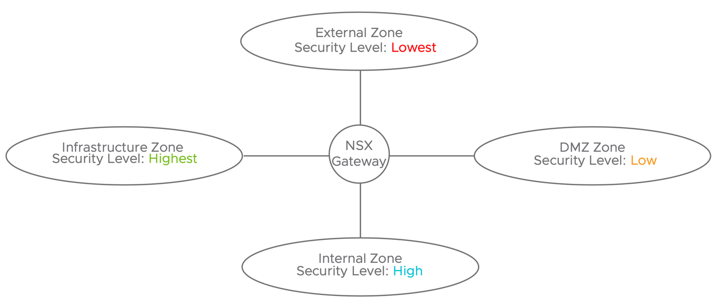
Figure 46: Logical Security Design
| # | Design Decision | Design Justification | Design Implication |
| DB.DD.27 | Incorporate a zone base security approach. | Zone base security provides similar functionalities to those provided by hardware appliances and a reasonable starting point to develop a more advanced security policy. It represents a compromise between acceptable risk and ease of management. | Critical workload may require a more restrictive policy. If necessary, it can be implemented via the distributed firewall capabilities of the DC in a Box. |
| DB.DD.28 | The External zone has no access to the DC in a Box resources. | The External Zone may represent an untrusted network such as the public Internet. | Custom NAT and firewall rules must be created to access the DC in a Box resources from the external zone. |
| DB.DD.29 | The DMZ zone does not have access to the Internal Zone | The DMZ zone hosts workloads at a higher risk to be compromised because they are exposed to the external network. They are for this reason isolated from the critical workload residing on the internal zone. | Distributed application may require connectivity to the internal network (i.e., web tier in the DMZ, database in the Internal zone). In this scenario granular access rules should be implemented for the DMZ to Internal flow, and a zero-trust approach should be considered for the component on the internal network. |
| DB.DD.30 | Workloads in the DMZ Zone are isolated from one another. | The DMZ zone hosts workloads at a higher risk to be compromised because they are exposed to the external network. Mutual isolation reduces the risk for an attack lateral movement. | If communication between components in the DMZ is required, granular rules should be implemented. |
| DB.DD.31 | The infrastructure zone is only accessible from the Internal Zone and no outbound connectivity is allowed from it | The infrastructure zone is the most critical area of the solution. Allowed inbound and outbound traffic should be minimized. | Patching or upgrading infrastructure components may require Internet connectivity from the infrastructure zone. Granular temporary access rules or offline uploads from the Internal zone should be considered in those scenarios. |
Table 21: DC in a Box - Security Logical Design - Design Decisions
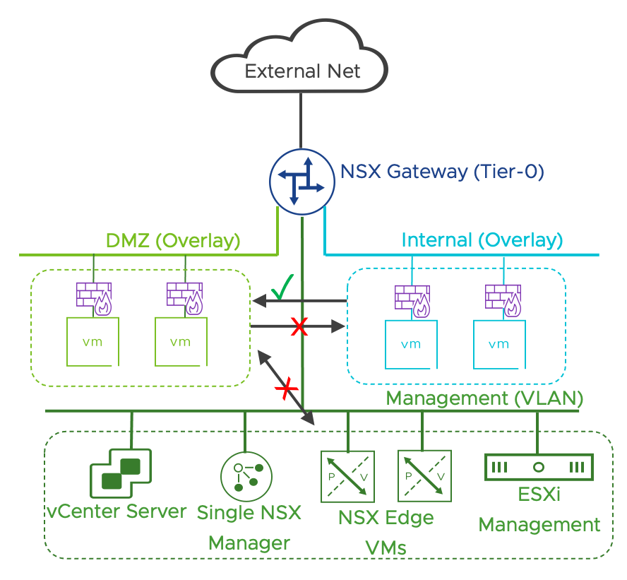
Figure 47: Internal Zone has access to DMZ zone, DMZ Zone does not have access to the other zones
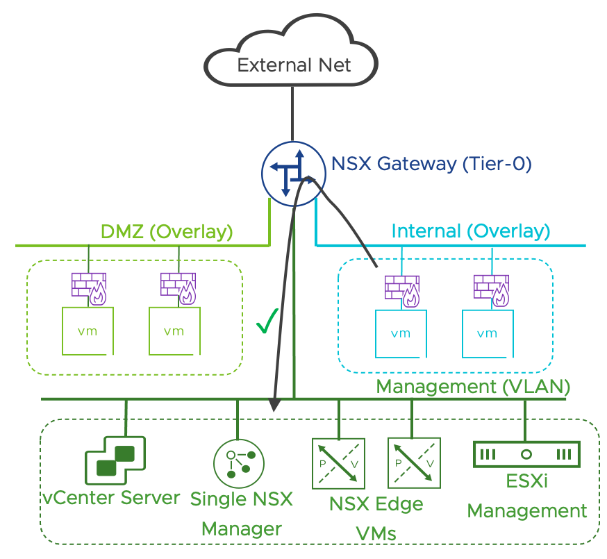
Figure 48: Internal Zone has access to the Infrastructure Management Zone
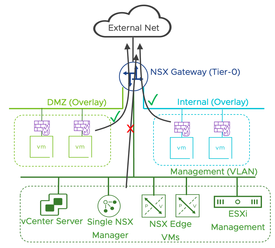
Figure 49: Internal Zone has access to the Infrastructure Management Zone, all zones can access the Internet except for the Infrastructure Management zone.
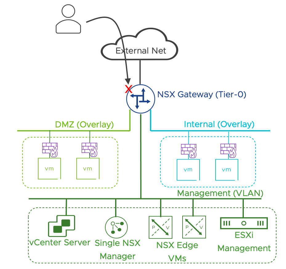
Figure 50: By default, no inbound external access is allowed
3.4.2.7 Gateway Firewall Design
The default Gateway Firewall configuration includes Inbound policy, Outbound policy, and Infrastructure access policy.
![]()
![]()
![]()
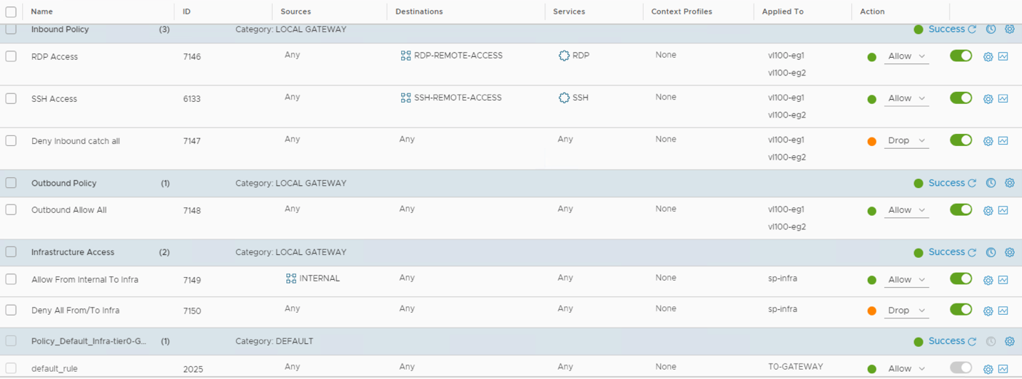
Figure 51: DC in A Box Default Gateway Policy
The Inbound Policy controls the traffic from the External Zone to the DC in a Box. All the rules in the inbound policy have a direction-setting of “in” and are applied to the uplink interfaces of the active and standby NSX Gateway. The inbound policy denies all traffic by default. The policy comes with two placeholder firewall rules configured to permit remote access via SSH or Microsoft RDP to workloads running in the datacenter in the box. The administrator can enable remote access by applying a tag to the workload (scope:remote, tag:ssh ; or scope:remote, tag:rdp), making it part of the appropriated group, and applying a DNAT for the IP of the workload.
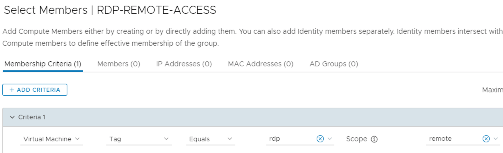
Figure 52: Membership Criteria for the RDP-REMOTE-ACCESS Group
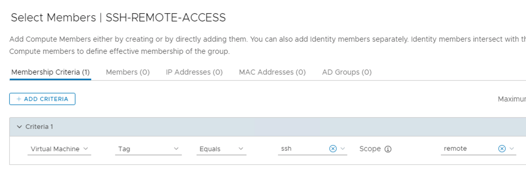
Figure 53: Membership Criteria for the SSH-REMOTE-ACCESS Group

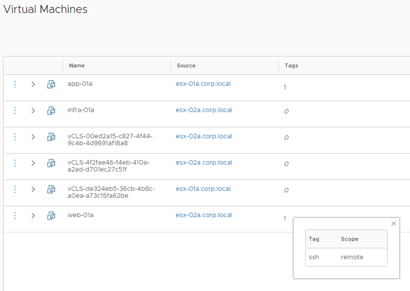
Figure 54: VM tagged to allow remote access via SSH
DNAT configuration must have the Firewall setting configured to “Match Internal Address” (Default) so that the Gateway Firewall allows that traffic based on the configured rules.
![]()
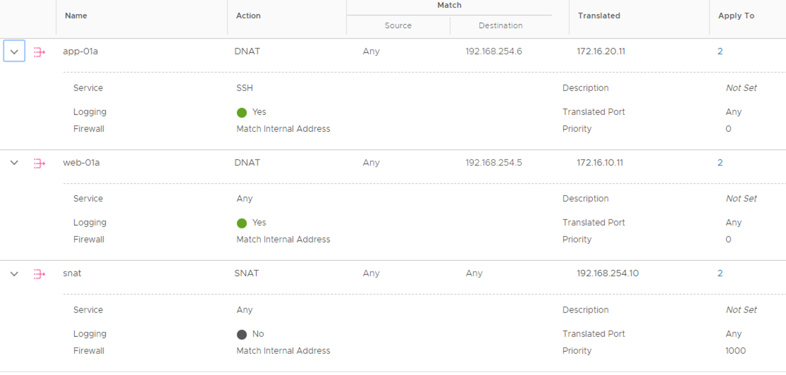
Figure 55: Example of DNAT configuration for Remote Access
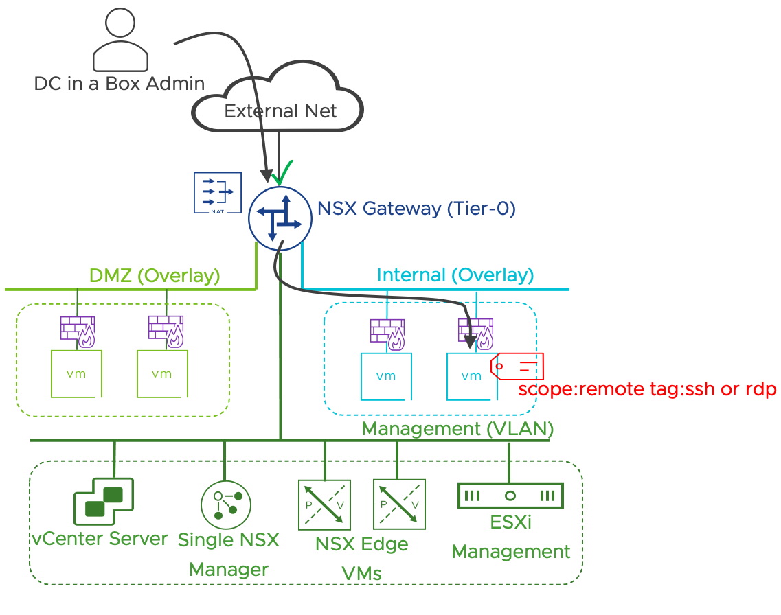
Figure 56: External Access enabled by tagging and NAT configuration
The Outbound Policy controls the traffic from the DC in a Box to the External network. All the rules in the outbound policy have a direction-setting of “out” and are applied to the uplink interfaces of the active and standby NSX Gateway. All outbound traffic is allowed by default. The NSX Gateway uses a SNAT rule for all the outbound traffic. The entire traffic out of the DC in a Box is by default hidden behind a single IP.
The Infrastructure Access Policy controls the traffic in and out of the infrastructure zone. The rules part of the policy are applied to the service interface connected to the infrastructure management VLAN. A rule allows the internal workload to access the infrastructure zone. A second rule denies any traffic from the infrastructure zone.
| # | Design Decision | Design Justification | Design Implication |
| DB.DD.32 | Use the Gateway firewall to control traffic to and from the External Zone | The Gateway firewall specifications and functionalities are appropriate to connect the DC in a Box to an untrusted network. | The Gateway Firewall enforces traffic control on uplink and service interfaces only. Those interfaces must be in the traffic path for the rules to be effective. |
| DB.DD.33 | Use a Gateway firewall service interface to control traffic to and from the Infrastructure VLAN. | Gateway Firewall rules applied to a service interface can control inbound and outbound traffic to the infra zone. Because the infrastructure VLAN includes physical components a service interface in an appropriate way of integrating it in the NSX Security model. | East/West traffic cannot be controlled within the Infrastructure VLAN. |
Table 22: Dc in a Box - Gateway Firewall Design Decisions
3.4.2.8 Distributed Firewall Design
Most of the DC in Box default security enforcement is performed at the Gateway Firewall level, making the DC in a Box security solution very similar to a traditional design based on hardware appliances. The Gateway firewall can enforce policy only on uplink and service interfaces, making it inadequate to control the DMZ and Internal network traffic, both connected to downlink interfaces. For this reason, the DMZ isolation policy is implemented at the Distributed Firewall Level.
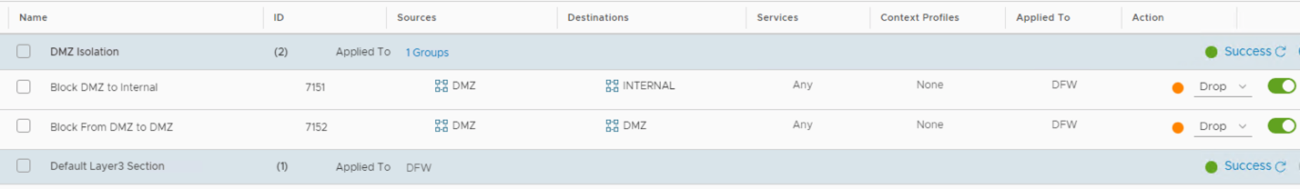
Figure 57: Distributed Firewall Implementation of the DMZ Isolation Policy
A DMZ and Internal groups are pre-created. Group membership criteria are based on segment tags. Any VM placed on the Internal network will be automatically part of the Internal Group. Any VM connected to the DMZ network will automatically be part of the DMZ Group.

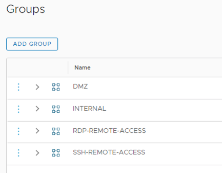
Figure 58: Default Groups Created as Part of the DC in a Box Solution
![]()
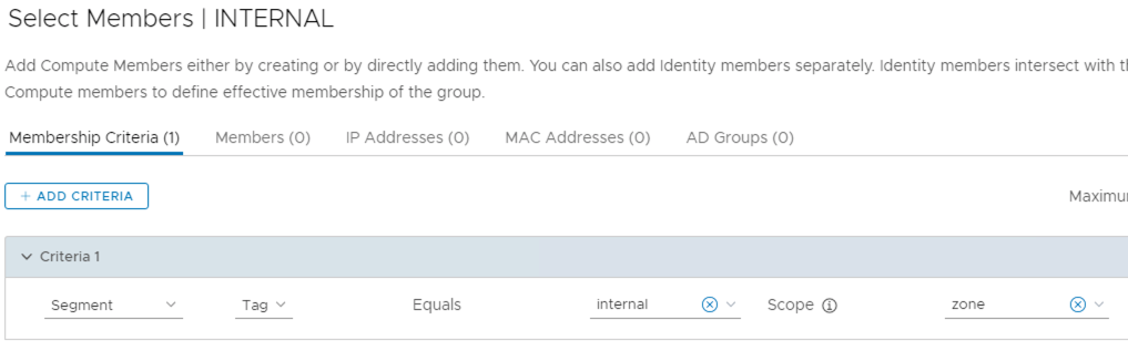
Figure 59: Membership Criteria for the Internal Group
| # | Design Decision | Design Justification | Design Implication |
| DB.DD.34 | The DMZ Isolation Policy is enforced at the Distributed Firewall Level | Distributed Firewall is required to filter traffic between two segments connected to the same NSX Gateway | Security configurations are split between Gateway Firewall and Distributed Firewall view in the NSX Manager UI. |
Table 23: Distributed Firewall Design Decision for the Datacenter in a Box Solution
3.4.3 NSX Application Platform (NAPP) Design – Optional
Follow the same guidelines as in the Simple Security for Application Use case. We recommend a deployment based on VDS networking even if NSX Overlays and Edge Nodes are available in the DC in a Box design. If the Tanzu environment is only leveraged for the NAPP deployment, we think that the simple deployment based on VDS networking is the most appropriate.
3.4.4 Next Generation Firewall Design – Optional
3.4.4.1 Use cases
The DC in a Box use case can be extended with the adoption of NSX Gateway firewall capabilities. NSX Distributed Security services should cover the requirements for advanced security services in most scenarios, but in some cases enabling the NSX Next Generation Firewall capabilities is the appropriate choice. Reasons to consider this option are:
- Additional layer of protection of North/South traffic. Distributed IPS, Malware Prevention, and Network Traffic Analysis are already in place for East-West traffic. The Next Generation firewall capabilities provide an extra layer of protection.
- SSL Decryption. SSL decryption and the ability to leverage advanced security services such as IPS on encrypted traffic is not currently available for distributed services. Still, it is on the Next Generation gateway Firewall.
- URL Filtering. URL Filtering based on categories and reputation is only available on the Next Generation gateway Firewall
- Advanced security services are required for N/S traffic. In some cases, enabling advanced security features on the Next Generation gateway Firewall may be more cost-effective if East /West traffic is not in scope.
3.4.4.2 Detailed Design
In NSX 3.2, Next Generation Firewall capabilities are only available on Tier-1 gateways. Tier-0 Gateway provides Layer-4 firewall capabilities. In this design, we keep using the Tier-0 gateway part of the original DC in a Box design for Layer 4 firewalling. All the gateway firewall policies configured on the Tier-0 gateway remain unchanged. We introduce a Tier-1 Gateway to the topology where we can deploy the available advanced security services. We will connect the Tier-1 gateway to the original Tier-0 gateway and host layer-7 App-Id rules, IPS policies, malware detection rules, SSL Decryption policies, and URL filtering capabilities. Moving the segments from the Tier-0 Gateway to the Tier-1 Gateway will be required to leverage the services and policies configured on the Tier-1 gateway. The operation is non-disruptive.
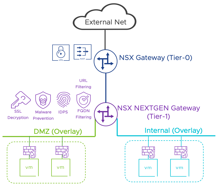
Figure 60: Extending the DC in a Box Use case with Next generation Firewall capabilities
| # | Design Decision | Design Justification | Design Implication |
| NGFW.DD.1 | We will deploy a new Tier-1 Gateway for next generation firewall capabilities | Next Generation Firewalls capabilities are not available on the existing Tier-0 gateway | Workload segments must be connected to the Tier-1 gateway for next generation firewall capabilities to be available. |
| NGFW.DD.2 | The Tier-1 Gateway will be connected to the existing Tier-0 Gateway | Workloads connected to the Tier-1 Gateway need access to the external network | N/A |
| NGFW.DD.3 | No Layer 4 policies will be migrated to the Next Generation Tier-1 Gateway. We will keep Layer 4 enforcement on the Tier-0 Gateway. | No need for migrating the policies. Clear separation between L4 and L7 rules Simpler Next Generation Firewall configuration. Seamless adoption of advanced security services | Configuration is split across two locations May need to duplicate some rules |
| NGFW.DD.4 | FQDN Visibility is the only Layer7 service enabled by default | FQDN Visibility can be implemented transparently | FQDN Visibility requires a DNS Layer7 rule to perform DNS snooping The implementation of additional advanced security services is manual |
Table 24:Next Generation Firewall Design Decision for the Datacenter in a Box Solution
3.4.5 NSX Advanced Load Balancer Design – Optional
It is possible to extend the DC in a Box with the services provided by the NSX Advanced Load Balancer following the general guidance provided in the official documentation and in the dedicated design guide.
Virtual IPs are deployed internally to the DC in a Box, so a Destination NAT configuration on the DC in a Box NSX gateway (Tier-0) is required to access them by external clients.
Design decisions specific to the DC in a Box deployment are outlined in the table below.
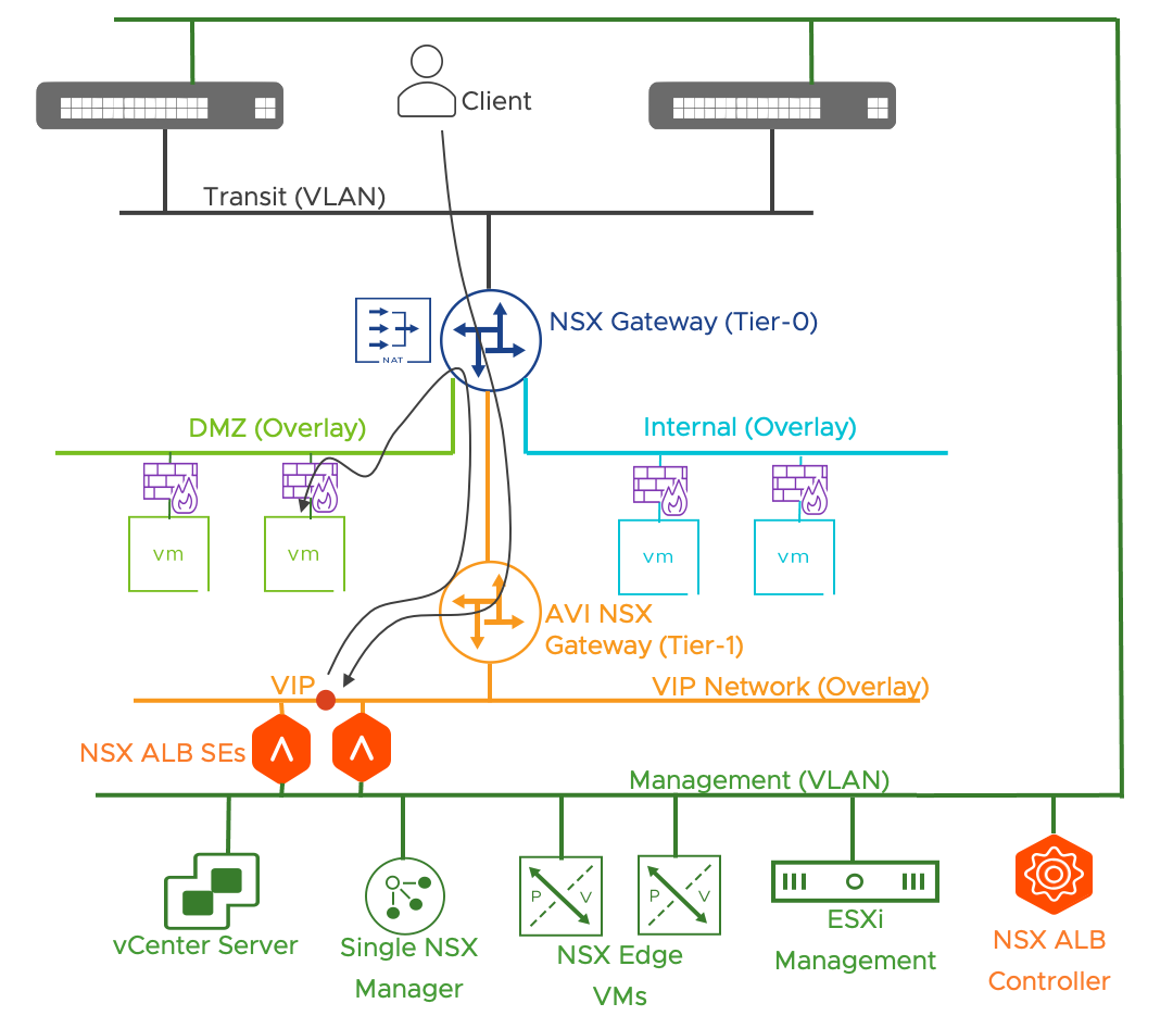
Figure 61: NSX Advanced Load Balancer in the DC in a Box Use case
| # | Design Decision | Design Justification | Design Implication |
| AVI.DD.1 | Deploy a single Advanced NSX Load Balancer controller VM in the DC in a Box collapsed vSphere cluster. | A single Advanced NSX Load Balancer controller VM minimizes the resources required to implement the solution. | During an Advanced NSX Load Balancer outage the failure of one SE will not be recovered by another SE. The controller component is required to reconfigure the VIP static routes on the Tier-1 gateway. |
| AVI.DD.2 | Protect the single NSX Advanced Load Balancer Controller VM using vSphere High Availability. | vSphere HA will provide basic level of redundancy to the NSX Advanced Load Balancer management plane | The NSX Advanced Load Balancer management plane is not available until the Controller VM is fully restarted on a different host |
| AVI.DD.3 | Create an NSX-T Cloud Connector on NSX Advanced Load Balancer Controller and integrate it with the DC in a Box NSX Manager. | The NSX-T Cloud Connector simplifies the consumption of the NSX Advanced Load Balancer services | VIP IPs are internal to the DC in a Box. Providing access to the VIPs to external clients requires creating a DNAT on the Tier-0 NSX gateway. |
| AVI.DD.4 | Create a T1 Gateway dedicated to the NSX Advanced Load Balancer deployment and connect it to the DC in a Box T0 Gateway. Do not specify an edge cluster. | It is required by the NSX-T Cloud Connector. The NSX Advanced Load Balancer dynamically configure /32 static routes for each VIP. Stateful services are not required on this Tier-1 gateway, so no edge cluster must be specified. | An additional NSX Gateway component must be created. |
| AVI.DD.5 | On the Tier-1 Gateway, configure route advertisement to include connected, static, and load balancer VIP routes. | Required to provide connectivity to the VIPs | N/A |
| AVI.DD.6 | SE VMs will have their management network on an NSX VLAN segment with the same VLAN ID as the management distributed port-group (VLAN). | The NSX-T Cloud Connector requires SE management interfaces to be placed on an NSX Segment, VLAN or Overlay. Placing the SE on the management network allow for direct communication between the SE and the controller without traversing the DC in a Box NAT boundary. | IPs must be available on the DC in a Box Management Network (2 minimum, 4 or more recommended). Additional NSX Segment must be created and associated with the ESXi Hosts VLAN Transport Zone. |
| AVI.DD.7 | The NSX Advanced Load Balancer Controller will allocate the SE Management IP Addresses from a pool | Avoid dependencies on the physical network (i.e., DCHP server) | IPs must be available on the DC in a Box Management Network (2 minimum, 4 or more recommended). |
| AVI.DD.8 | SE VMs will have their data network (the network where the VIPs reside) connected to an overlay segment connected to the T1 Gateway dedicated to the NSX Advanced Load Balancer deployment. | VIPs will be allocated from an IP space within the DC in a Box NAT boundary. Avoid the need to allocate external IPs unless the VIP must be exposed externally. | DNAT is required when exposing the VIPs externally |
| AVI.DD.9 | The overlay segment dedicated to the AVI SE VIPs will be added to a group part of the DFW exclusion list | Avi SE redirects traffic from the primary SE to secondary SEs when using L2 scale-out mode. This leads to asymmetric traffic which can get blocked by the Distributed Firewall because of its stateful nature (TCP Strict Enable) | AVI SEs should not share the VIP segment with any workload. |
Table 25: NSX Advanced Load Balancer Design Decision for the Datacenter in a Box Solution
4 Appendix
4.1 Outside References
VMware NSX official product documentation
https://docs.vmware.com/en/VMware-NSX-T-Data-Center/index.html
VMware NSX Design Guide
https://communities.vmware.com/t5/VMware-NSX-Documents/VMware-NSX-T-Reference-Design/ta-p/2778093
VMware NSX Security Reference Guide
NSX Security Quick Start Guide
VMware NSX data sheet
VMware Gateway Firewall data sheet
Product offerings for NSX 3.2 Security
https://kb.vmware.com/s/article/87077
DC in a Box Automation
https://github.com/vmware-nsx/dcinabox/tree/3.2.1
NSX Application Platform Automation Guide
https://via.vmw.com/napp-automation-guide
NSX Application Platform Automation Appliance
https://via.vmw.com/napp-automation-ova
NSX Application Platform Deployment Guide
https://via.vmw.com/napp-deployment-guide
AVI and NSX-T Best Practices